Capacitance is the ratio of charge stored on a conductor pair to the voltage between them:
Two conductors carrying and at potential difference form a capacitor. depends only on geometry (sizes, shapes, spacing) and the Permittivity of the dielectric between, not on or separately. Pushing more charge raises the voltage in proportion; the ratio stays fixed.
Parallel-plate capacitor
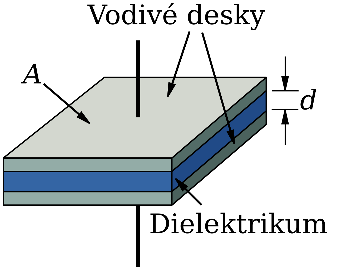 Image: Parallel plate capacitor, CC BY-SA 4.0 — parallel-plate capacitor with uniform field between the plates.
Two parallel conducting plates of area separated by distance , with dielectric of permittivity :
Derivation: charges distribute quasi-uniformly on the plates with surface density . Inside the dielectric, is approximately uniform from the conductor boundary condition , giving . Voltage between plates: . Capacitance:
The approximation neglects fringing fields at the edges; valid when plate dimensions are much greater than separation .
Coaxial capacitor
Two concentric cylindrical conductors, inner radius , outer radius , length , dielectric between. Four steps, each an instance of a method that recurs throughout electrostatics.
Step 1 — Charge on the conductors. Put on the inner conductor; by induction accumulates on the inner surface of the outer conductor. Treat both as uniform line charge densities on the inner conductor (using much greater than , so end effects are negligible).
Step 2 — Field by Gauss’s law. Cylindrical symmetry → inside the dielectric. Use a cylindrical Gaussian surface of radius () and length coaxial with the conductor pair. Flux through curved side: . Caps contribute zero. Enclosed charge: . So
The fall-off is characteristic of cylindrical symmetry.
Step 3 — Voltage from . Integrate along a radial path from inner conductor () to outer ():
Sign convention: when the inner conductor is at higher potential. Direction of integration is from low to high potential, picking up the negative sign on .
Step 4 — Capacitance. Divide:
Capacitance per unit length: (F/m). This is one of the parameters that defines a coaxial Transmission line.
Sanity checks. Capacitance scales linearly with length, as expected for a uniform structure. The factor diverges as (a thin inner wire concentrates field near the axis) and as (the outer conductor recedes, V grows logarithmically). Doubling doubles : more dielectric polarization → more stored charge per volt.
Concentric sphere capacitor
Inner radius , outer radius , dielectric . By Gauss with spherical symmetry:
Capacitance:
Taking gives the capacitance of an isolated sphere: .
RC product relation
For any two-conductor geometry with the same dielectric filling, the resistance of the dielectric (treating as the leakage conductivity) and the capacitance satisfy
This holds independent of geometry. Proof sketch: both and depend on the same pattern via integrals that share the geometry, so their product collapses to a material-only constant. Lets you predict one from the other (find from electrostatics, then for the leakage path).
The ratio is the dielectric relaxation time, the time scale on which free charges placed inside a conductor relax to the surface. For copper, this is sub-femtosecond. For mica, ~15 hours.
General formula
For arbitrary geometry, capacitance can be computed from the field:
where is any surface enclosing the conductor and is any path from conductor 2 to conductor 1.
Energy stored
Energy stored in a capacitor charged to voltage with charge :
Derivation: bring charge in increments at instantaneous voltage , total work .
This energy lives in the electric field inside the dielectric, with energy density