The canonical example for the whole signals-and-systems framework: a chain of subsystems that takes a message, encodes it as a signal, pushes it through a noisy physical medium, and recovers the message at the other end.
The standard block diagram has three pieces:
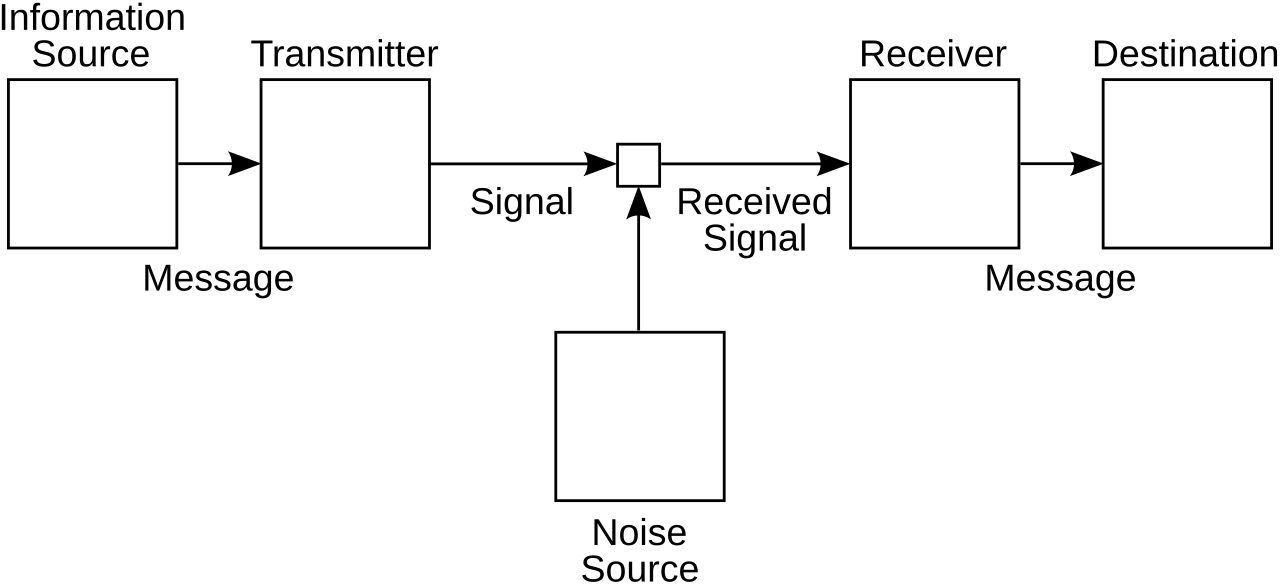 Image: Shannon communication system, public domain
The transmitter encodes the message (text, audio, video) into a physical signal: voltages on a wire, light pulses in a fiber, radio waves through space. The channel is the medium the signal travels through; it can attenuate, distort, delay, and add noise. The receiver interprets the (possibly damaged) signal and recovers the original message.
Why this example anchors the course
Every individual tool we develop has its place in some part of this picture. When we study filters, we’re asking how to design receivers that throw away noise but keep the message. When we study the Fourier transform, we’re asking how to represent a signal in a form that separates “message” from “noise.” When we study sampling, we’re asking how to convert a continuous signal into discrete numbers we can ship through a digital link.
A real satellite link is this picture in extreme detail: the modem and transmitter have bandlimiting loss, intermodulation, AM/PM conversion, oscillator phase noise; the antenna has efficiency and radome loss; the channel has pointing loss, polarization loss, atmospheric/rain loss, free-space loss; the receiver has its own losses and noise sources, plus co-channel and adjacent-channel interference; the receiving modem has intersymbol interference and synchronization jitter. End to end, a dozen subsystems chained together, each doing something deterministic and each adding noise.
We don’t study any of these specific blocks in this course. We study the general theory that lets us model and analyze any block of this kind, and then chain them.
The bit-recovery problem in miniature
Suppose we want to send the ASCII text “SIGNAL” over a wire as a binary voltage waveform (0 V for a 0, 5 V for a 1). On a clean wire with no noise, the receiver just samples the voltage in the middle of each bit period and reads off the bits.
Now add noise. At high signal-to-noise ratio the rectangles are still visible with a little hash on top; at moderate SNR the edges get fuzzy; at low SNR the rectangles disappear into the hash, and you can’t tell where one bit ends and the next begins by eye.
How does a real receiver recover the bits? It filters the noisy signal (passes it through a system designed to suppress noise more than signal) and then compares the filtered output to a threshold at each bit time. Above threshold 1; below 0. Even when the unfiltered signal looks like pure noise, a well-designed filter can recover the bits with very few errors. That one fact is what the second half of the course is about.