A phasor is a complex number that represents the amplitude and phase of a sinusoid. The trick: replace each sinusoidal voltage or current with the complex number . The time dependence drops out, and circuit analysis becomes algebra in .
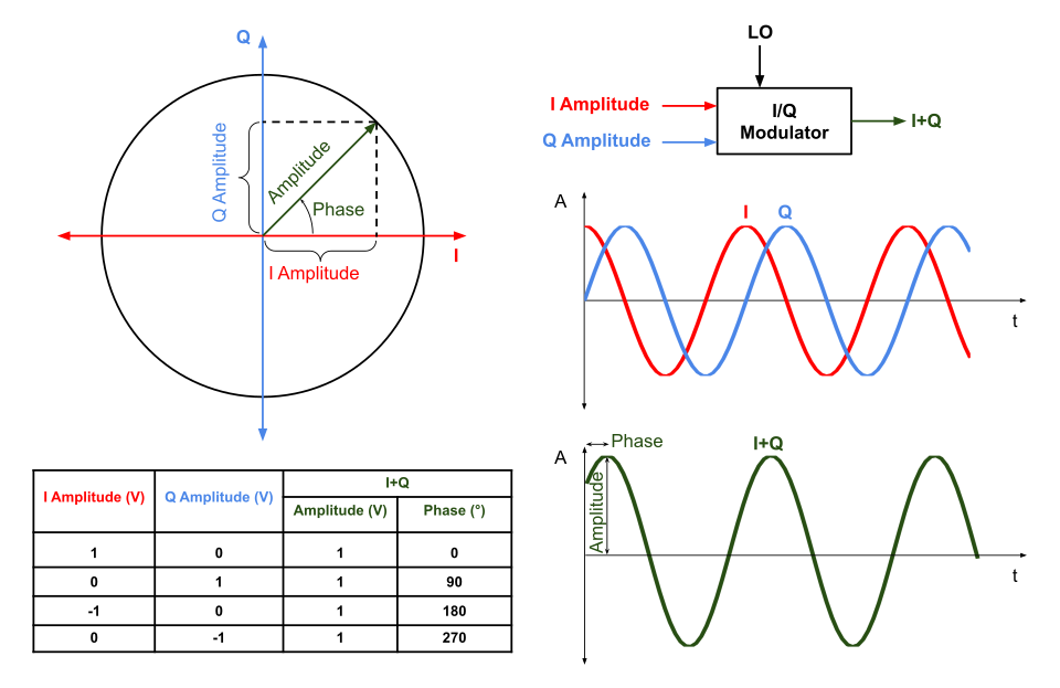 Image: Phasor diagram with the resulting time-domain waveform, CC BY-SA 4.0
(Electrical engineering uses instead of for the imaginary unit, since is reserved for current.)
Notation
Three equivalent forms for a phasor :
- Rectangular: .
- Polar: (read ” at angle ”).
- Exponential: .
With the correspondences:
The argument formula must be , not . The plain returns values only in , so it can’t distinguish second-quadrant phasors from fourth-quadrant ones (or third from first). The two-argument inspects the signs of and separately and returns the correct angle in regardless of quadrant. Forgetting this is the most common bug when computing phasor arguments by hand from rectangular form.
The exponential form follows from Euler’s formula (Polar representation of complex numbers).
Time-domain ↔ phasor
The map between sinusoid and phasor:
Note the convention: cosine is the reference. A sine becomes a cosine via , so the phasor of a sine has its phase shifted by .
To recover the time-domain signal:
The phasor encodes amplitude and phase; multiplying by adds the time dependence; taking the real part recovers the actual voltage.
Why phasors work
Linear circuit equations involve derivatives of and . For sinusoids:
Differentiation does two things at once: shift the phase by and scale the amplitude by . In phasor form both fall out of a single multiplication, since differentiation is multiplication by . The adds the phase shift, the scales the magnitude. Don’t drop either; at high frequency the magnitude scaling dominates.
Integration is division by , which shifts the phase by and divides the magnitude by .
So derivatives and integrals, the hard part of circuit analysis, become algebraic operations on complex numbers. Differential equations in time become algebraic equations in .
This only works for steady-state sinusoidal signals. Transients (right after a switch closes, before steady state is reached) need time-domain analysis or the Laplace transform.
Phasor arithmetic
Add phasors when summing voltages or currents at a node:
Multiply phasors when computing products (e.g., , with impedance as a complex number):
Use rectangular form for sums; polar/exponential form for products. Convert between as needed.
Example
A voltage has phasor .
A current . Convert to cosine reference: . Phasor: .
Both can now be combined algebraically as circuit equations in the frequency domain.
In context
Phasor analysis underlies AC electric circuits. It assumes sinusoidal steady state, meaning the system has settled into equilibrium with the sinusoidal source. For transients, use the Laplace transform, which generalizes phasors by including decay rates. For how R, L, and C are represented as phasors, see Phasor relationships for circuit elements.