An I/O device interface is the circuit that sits between an I/O device (keyboard, display, disk) and the processor’s interconnection network. It exposes the device to the processor as a small set of memory-mapped registers, and ferries data between processor and device.
Most interfaces have three registers:
- DATA register: holds the data byte being transferred to or from the device.
- STATUS register: flags telling the processor what state the device is in.
- CONTROL register: bits the processor sets to configure device behavior.
The processor reads and writes these registers as if they were ordinary memory locations; they live at fixed addresses in the address space. This is memory-mapped I/O, the standard scheme on RISC machines.
Example: keyboard and display
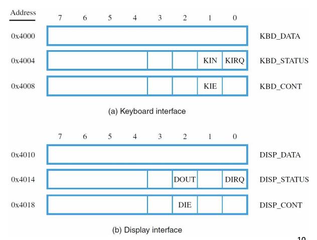
For the textbook keyboard at addresses –:
| Register | Address | Meaning |
|---|---|---|
KBD_DATA | The ASCII character read from the keyboard | |
KBD_STATUS | KIN flag (bit 1): 1 when a character is ready | |
KBD_CONT | KIE flag (bit 1): 1 to enable keyboard interrupts |
The KIN flag goes high when a key is pressed and a new character has loaded into KBD_DATA. Reading KBD_DATA automatically clears KIN: the act of reading consumes the character and tells the device “OK, ready for the next one.”
For the display at –:
| Register | Address | Meaning |
|---|---|---|
DISP_DATA | Character to be displayed | |
DISP_STATUS | DOUT flag (bit 2): 1 when display ready for new character | |
DISP_CONT | DIE flag (bit 2): 1 to enable display interrupts |
DOUT is the inverse direction: it’s high when the display is ready to accept a new character. Writing to DISP_DATA clears DOUT (the display is now busy processing the new character).
Why the three registers
- DATA is the physical conduit. Bytes flow through it.
- STATUS is what the processor reads to decide whether the device is ready. Without status, the processor would never know when to read or write data.
- CONTROL is what the processor writes to configure the device. Enable interrupts, set baud rate, change mode, etc.
The split lets the processor poll status without disturbing data, and configure once at boot without re-checking every transfer.
Two ways to use it
The processor can interact with the interface in two modes:
-
Polling: read STATUS in a loop until ready, then read/write DATA. Simple, but the processor wastes cycles spinning while the device gets ready.
-
Interrupts: configure the device’s CONTROL register to raise an interrupt when status changes. Processor goes off and does other work; the ISR handles the device when it interrupts.
Polling is simpler; interrupts are more efficient when the processor has other work to do.
Memory-mapped vs. port-mapped
The scheme above is memory-mapped I/O: device registers live in the same address space as memory. Reading address gets the keyboard character; reading address might get a value from RAM. The processor can’t tell the difference; the address bus carries both.
x86 also supports port-mapped I/O, where I/O has its own separate address space accessed by special IN and OUT instructions. RISC machines like Nios II don’t have port-mapped I/O, they use memory-mapped exclusively.
Memory-mapped is simpler from a software perspective: any load/store instruction can talk to a device, no special instructions needed. The downside: you have to be careful not to cache I/O addresses, since their values change unpredictably (the keyboard data changes whenever a key is pressed, not based on processor activity).