There are two ways a clocked storage element can sense its control signal: by level or by edge. The choice determines when the storage updates relative to the clock and is the key difference between a latch and a flip-flop.
Level-triggered
A level-triggered (or level-sensitive) element responds to its inputs as long as the control signal is at its active level. While the gate (clock, enable, etc.) is high, the element is “transparent”: its output tracks its input.
A gated D latch is the canonical example. While Clk = 1, follows , so every change in propagates through. While Clk = 0, the latch holds.
The downside: any glitch on during the active level passes straight to . In a chain of latches with a shared clock, signals can race through multiple stages within a single clock pulse, doing more work than intended.
Edge-triggered
An edge-triggered (or edge-sensitive) element samples its input only at the transition of the control signal. Once captured, the value is held until the next triggering edge. No transparency, no glitches between edges.
Two flavors based on which transition triggers:
- Positive-edge triggered: samples on the rising edge ().
- Negative-edge triggered: samples on the falling edge ().
In schematic symbols, an edge-triggered input is marked with a small triangle (▷) on the clock input. A bubble in front of the triangle (▷○) marks negative-edge.
A standard D flip-flop is the canonical edge-triggered element. Modern synchronous design is built almost entirely from positive-edge triggered D flip-flops, since the predictability of “exactly one update per clock cycle” makes timing analysis tractable.
Side-by-side
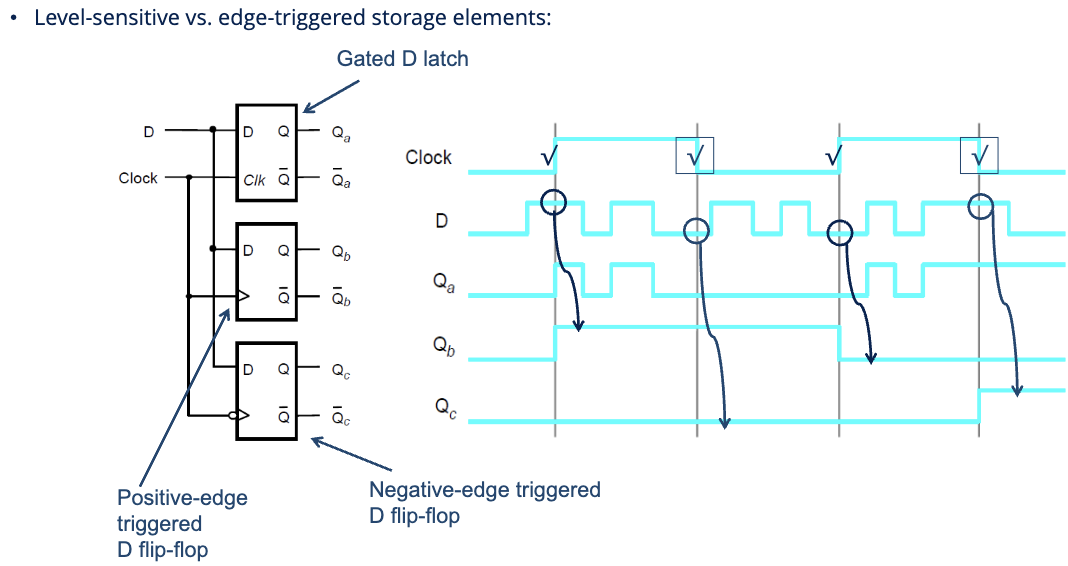
The diagram shows three storage elements all driven by the same Clk and :
- — gated D latch. Transparent when Clk = 1; you can see tracking during high phases.
- — positive-edge triggered D flip-flop. Updates only at rising edges.
- — negative-edge triggered D flip-flop. Updates only at falling edges.
Notice how the latch’s output changes multiple times per clock period (once for each change during the high phase), while the flip-flops change at most once per clock period.
Picking which to use
For new synchronous designs: edge-triggered. Almost always. The behavior is predictable, timing analysis is tractable, and it composes cleanly. Timing constraints are well-defined around the edge.
Latches still appear in two contexts:
- As building blocks inside edge-triggered flip-flops (the leader-follower D flip-flop is two latches in series).
- In specialized low-power or interface circuits where transparency is actually wanted (data flowing through during the enable phase).
For everyday counter, FSM, or pipeline design: pick a positive-edge triggered D flip-flop and don’t think twice.