A latch is the simplest digital storage element. It holds a single bit of state and is level-sensitive: its inputs can affect the output any time they’re applied, not just at clock edges. That distinguishes it from a flip-flop, which only updates on a clock edge.
A latch is built from a small piece of combinational logic arranged with a feedback loop, which is what gives it memory.
Basic SR latch
The simplest latch is the basic SR latch, formed from two cross-coupled NOR gates:
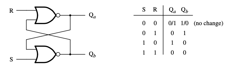
Two inputs ( and , for “set” and “reset”) and two outputs ( and , intended to be complements).
| Behavior | ||||
|---|---|---|---|---|
| 0 | 0 | previous | previous | hold (no change) |
| 0 | 1 | 0 | 1 | reset |
| 1 | 0 | 1 | 0 | set |
| 1 | 1 | 0 | 0 | forbidden |
When both and are , the latch holds whatever state it was in before; the feedback maintains it. The hold-row entries say “previous”: if the latch was previously set () it stays set; if previously reset () it stays reset. The truth table can’t write a single value here because the row’s behavior depends on history, which is the whole point of a memory element. When , is forced to and to ; when , the opposite.
The case is the forbidden state: both outputs go to , breaking the ” and are complements” invariant. Worse, when and both transition back to at the same time, the final state is unpredictable. A race condition in the gate delays decides which output settles to . Don’t drive both inputs high simultaneously.
Basic latches respond to input changes immediately, with no clock control. That makes them fast but unsuitable for synchronous design where you want all storage updates to happen at well-defined moments.
Gated SR latch
A gated SR latch adds a clock (or enable) input that gates when and can affect the latch:
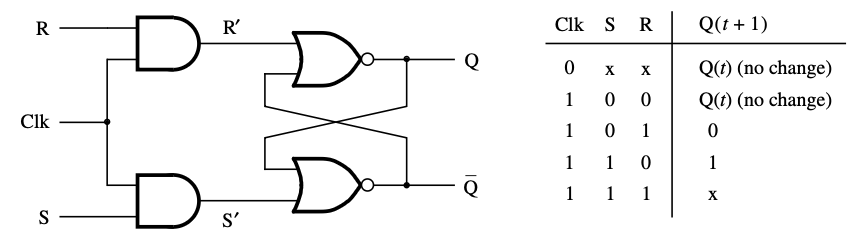
Two AND gates qualify and with the clock. When clock is , and the latch holds its state regardless of the actual and inputs. When clock is , the gated and pass through and the latch behaves like a basic SR latch.
| Clk | |||
|---|---|---|---|
| 0 | x | x | (no change) |
| 1 | 0 | 0 | (no change) |
| 1 | 0 | 1 | 0 |
| 1 | 1 | 0 | 1 |
| 1 | 1 | 1 | x (forbidden) |
The forbidden state is still there — gating and doesn’t fix the underlying problem of asserting both. The fix is the gated D latch.
Gated D latch
A gated D latch eliminates the forbidden state by tying and . The two are always complements, so the case is now impossible:
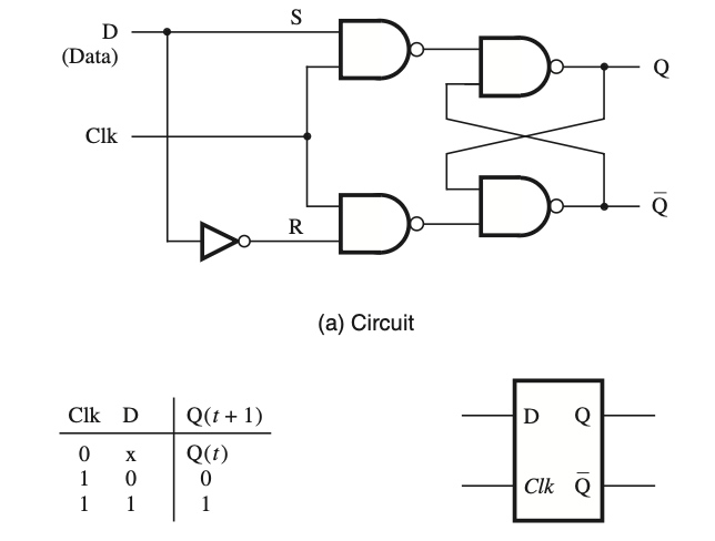
| Clk | ||
|---|---|---|
| 0 | x | |
| 1 | 0 | 0 |
| 1 | 1 | 1 |
When clock is high, follows : the latch is “transparent.” When clock is low, holds its last value.
This transparency during the high phase of the clock is the defining property of a level-sensitive latch, and also its main weakness for synchronous design. Any change in during clock-high will propagate to immediately, so chains of latches can glitch through more states than intended in a single clock cycle. The fix is edge-triggered flip-flops, which only sample the input at a clock edge.