A JK flip-flop generalizes the SR latch by giving meaning to the previously-forbidden state (): on that input it toggles, behaving like a T flip-flop.
| 0 | 0 | (hold) |
| 0 | 1 | 0 (reset) |
| 1 | 0 | 1 (set) |
| 1 | 1 | (toggle) |
So acts like Set, acts like Reset, together acts like Toggle, and holds. No forbidden states.
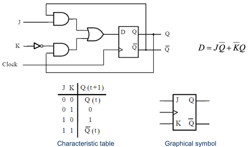
This four-row truth table is captured compactly by the JK characteristic equation:
You can verify each row by substitution: gives , gives , gives , gives . The characteristic equation is the standard FSM specification of the device. You’ll see analogous equations for D () and T ().
Implementation as a D flip-flop with the right input expression:
Verifying:
- : → hold.
- : → reset.
- : → set.
- : → toggle.
With the right wiring, it can mimic D, T, or SR behavior, all from the same physical flip-flop.
When to use it
JK is sometimes called a “universal” flip-flop because it can implement all the others by tying inputs:
- D behavior: , .
- T behavior: .
- SR behavior: , (with now meaning toggle instead of forbidden, different semantics but useful in some FSMs).
In practice, modern designs use D flip-flops almost exclusively. The synthesis tool maps any behavior you describe in VHDL onto D flip-flops with appropriate combinational logic. JK matters historically (it was popular in TTL designs of the 1970s–80s) and shows up in textbook problems but rarely in current engineering practice.
The downside of JK: two inputs instead of one means more wiring and more potential for input glitches when and both change near a clock edge.