A T flip-flop (“T” for toggle) has a single input . On each clock edge, if the flip-flop toggles its output (flips ); if , it holds.
| 0 | |
| 1 |
Implementation is a D flip-flop with :
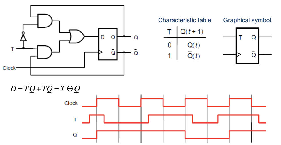
When : , so stays the same on the next clock edge. When : , so flips.
The defining algebraic equation:
Where they’re useful
T flip-flops are awkward for general-purpose storage but good for one job: counters. A chain of T flip-flops with tied high produces a binary counter. Each stage toggles at half the rate of the stage below it, giving a binary count sequence.
For an asynchronous up-counter, wire each to the next stage’s clock input. The bits ripple: bit 0 toggles on every external clock, bit 1 toggles when bit 0 falls, bit 2 toggles when bit 1 falls. Counter (digital) has the full structure.
For other purposes, T is inferior to D (cleaner semantics) or JK (which generalizes T’s toggle behavior).
Usage status
T flip-flops aren’t sold as standalone parts much anymore. Synthesizers and libraries prefer to compose toggle behavior from D flip-flops with explicit XOR feedback. The T model is still useful for thinking about counter design, but in practice you’d describe the behavior in VHDL and let the tool generate the underlying gates.
The behavior is also a special case of the JK flip-flop: tying makes a JK flip-flop behave identically to a T flip-flop.