A counter is a sequential circuit that increments (or decrements) its stored value on each clock edge. It’s used to count events, generate timing intervals, and track elapsed time.
Counters can be wrapped with an enable input. When enable is low, the counter holds its current value instead of advancing.
Asynchronous (ripple) counter
An asynchronous counter chains T flip-flops (or D flip-flops wired to toggle), with each stage’s output feeding the next stage’s clock input.
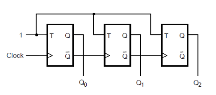
For a 3-bit up-counter:
- The external clock toggles bit 0 () on each cycle.
- Each falling edge of toggles (so runs at half the speed of ).
- Each falling edge of toggles (running at one-quarter speed).
The result is a binary count on .
For a down-counter using negative-edge-triggered flip-flops (the convention assumed throughout this section), drive the next stage from instead of . With positive-edge flip-flops the rule flips: drive the next stage from for an up-counter and for a down-counter is not how it works — instead positive-edge needs the inverter on the up-counter’s path. The principle is the same in both cases: pick the chosen edge of the lower bit so that it lines up with the cycle on which the higher bit should toggle. Always confirm which edge convention the diagram uses before reading off the rule.
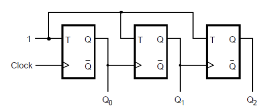
The same circuit now counts down to then wraps.
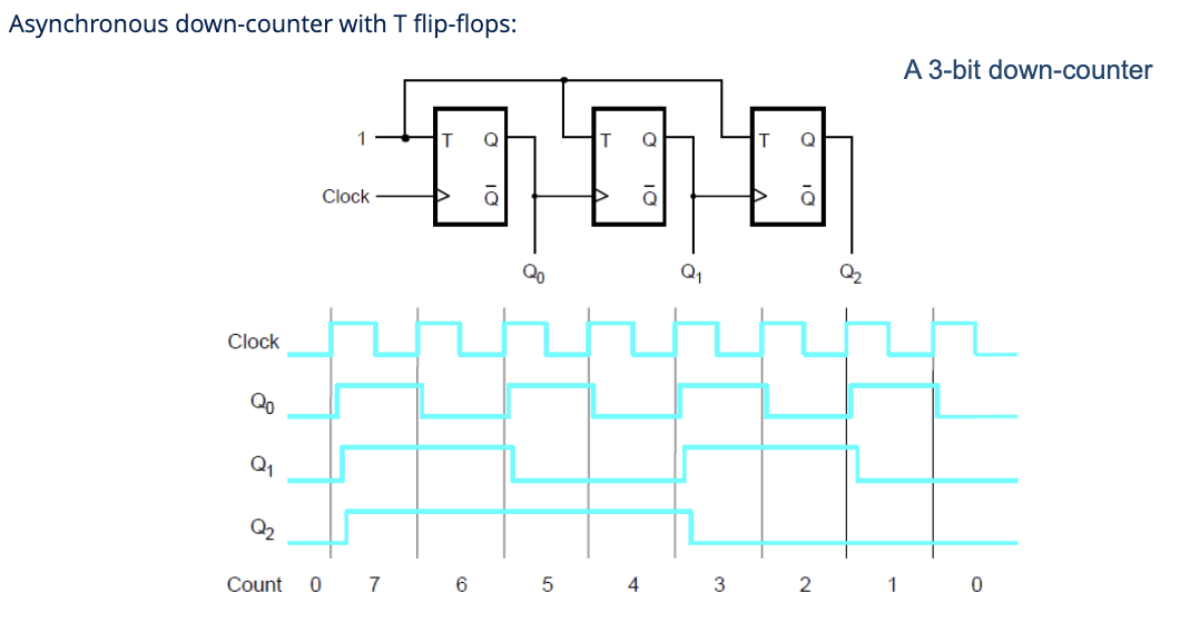
The timing diagram shows the bits’ transitions cascading down: bit 0 toggles every clock, bit 1 toggles when bit 0 falls, and so on.
Why “ripple”
Each stage triggers the next, so a transition at the LSB ripples through all higher bits one stage at a time. After the external clock edge, bits don’t all change simultaneously: bit 0 changes first, then bit 1 a flip-flop delay later, then bit 2, and so on.
For a 32-bit counter, bit 31 might lag bit 0 by 32 propagation delays. During the ripple, the counter’s output is briefly wrong: it shows intermediate values that aren’t valid counts. If you sample the output mid-ripple, you’ll get garbage.
This is the main weakness of asynchronous counters. They’re fine for slow displays or LED chasers but unsuitable when other logic needs the count value precisely at clock edges.
Synchronous counter
A synchronous counter drives all flip-flops from the same clock. Each stage’s input depends combinationally on the lower bits. For an up-counter, bit toggles only when all lower bits are .
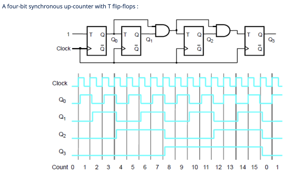
For a 4-bit up-counter:
- Bit 0: (always toggle).
- Bit 1: .
- Bit 2: .
- Bit 3: .
All four flip-flops fire at the same clock edge. Bits change together, so the count is always valid right after the propagation delay (no rippling).
The trade-off: you need extra AND gates to compute the toggle conditions, and the depth of those AND gates grows with bit width. For very wide counters, the AND-gate depth itself becomes a timing bottleneck, but that’s still much better than an -flip-flop ripple chain.
Picking one
- Asynchronous (ripple): simple, low transistor count, fine for slow applications. Don’t sample the output between clock edges.
- Synchronous: cleaner timing, valid output at every clock edge, slightly more hardware. Default for anything that interfaces with other synchronous logic.
Most CPU and FPGA counters today are synchronous. Async ripple counters mostly survive in microcontroller peripherals, watch chips, and clock dividers where simplicity matters more than precision.
A counter with a parallel-load input becomes a programmable counter: load any starting value, count from there. Useful for variable-period dividers and modulo-N counters.