A sequential circuit is a digital circuit whose output depends on both the current inputs and the history of past inputs. It contains storage elements that hold state between clock cycles, plus combinational logic that computes the next state and the outputs.
Contrast with combinational circuits, which are pure functions of their current inputs: no memory, no history. The moment you need a circuit to remember something, anything from a single button press to the current count of an event, you’ve moved into sequential territory.
A sequential circuit’s structure: combinational logic with a feedback path through one or more storage elements. The feedback is what creates memory.
Why memory matters
Consider an alarm system that must:
- Turn on when a sensor detects an event.
- Stay on even after the sensor returns to normal.
- Turn off only when manually reset.
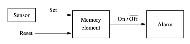
A pure combinational circuit can’t do this: the output would track the sensor in real time, going off the moment the sensor returned to normal. The behavior requires remembering that the sensor was triggered. A storage element (latch or flip-flop) holds that memory.
Anatomy
A sequential circuit has:
- A state, a configuration that summarizes the relevant past history. Stored in flip-flops; for flip-flops there are possible states.
- Inputs that, together with the current state, determine the next state and the outputs.
- A next-state function (combinational logic) that computes the next state from the current state and inputs.
- An output function (combinational logic) that computes the outputs.
- A clock signal in synchronous designs that defines when the state can change.
State changes can be described three ways: graphically by state diagrams, in tabular form by state tables, and algebraically by state equations (one Boolean equation per next-state bit). In practice you usually pick two of the three depending on the problem. The sequence-detector example uses a state diagram and state table but reads next-state logic off K-maps rather than state equations. The mathematical model behind all three is a finite state machine.
State machines come in two flavors based on how outputs are computed: see Mealy machine (outputs depend on state and inputs) and Moore machine (outputs depend only on state).
Synchronous vs asynchronous
Two ways to time a sequential circuit:
Synchronous
A synchronous sequential circuit changes state only at discrete instants, typically the rising or falling edge of a clock signal. All flip-flops share the same clock.
This is the standard. Synchronous circuits are easier to design (you only think about behavior at clock edges), more stable (the clock keeps things in sync across the chip), and easier to verify with timing analysis. Sometimes called clocked sequential circuits.
Asynchronous
An asynchronous sequential circuit changes state whenever the inputs change, no clock. Storage uses time delays (or just propagation delay through gates with feedback).
Asynchronous circuits are harder to design correctly because race conditions, hazards, and metastability can happen any time. Used when low latency matters more than ease of design (some interface circuits, ripple counters) or when there isn’t a clock available.
Storage elements
The two types of storage element used in sequential circuits:
- Latches — level-sensitive storage. Output follows input as long as a control signal is active.
- Flip-flops — edge-sensitive storage. Output changes only at a clock edge.
Designing one from a behavioral spec is worked through in Sequence detector (FSM design example); cutting redundant states is covered in State Reduction.