A Mealy machine is a finite state machine whose outputs depend on both the current state and the current inputs. The output is computed combinationally from the (state, input) pair, so it can react to input changes within the same clock cycle.
The contrast is the Moore machine, whose outputs depend only on the state.
Structure
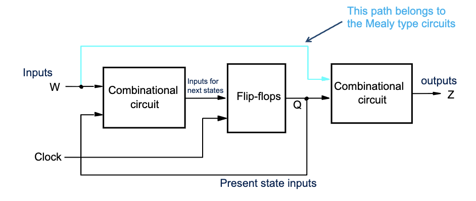
The cyan path in the diagram, from the input directly to the output combinational circuit, bypassing the state register, is what defines a Mealy machine. That path lets the output depend on the input within a single cycle.
Three pieces of combinational logic plus one state register:
- Next-state logic: takes (state, input) → next state.
- State register: flip-flops holding the current state.
- Output logic: takes (state, input) → output. This is the Mealy-specific piece.
Trade-offs vs Moore
Pros:
- Fewer states. Often needs one or two fewer states than the equivalent Moore machine, because outputs can change within a state based on input.
- Faster reaction. Output fires the same cycle the triggering input arrives; Moore would need an extra cycle to transition.
Cons:
- Output glitches. Because output depends combinationally on the input, any glitch on the input propagates to the output. Don’t drive a Mealy output to a downstream clocked device that latches on edges.
- Harder to verify. State diagrams have to label transitions with both input and output, which clutters the picture.
Drawing convention
In a Mealy state diagram, transition arrows are labeled input/output. The slash separates the condition that triggers the transition from the output that’s produced during the transition (or while the input is asserted, depending on convention).
For a Moore state diagram, output is labeled inside the state bubble and transition arrows just have the input condition.
Worked example
For the “detect two consecutive 1s” sequence detector:
- State A (idle):
- On input 0 → A, with output 0 on the transition.
- On input 1 → B, with output 0 on the transition.
- State B (just saw a 1):
- On input 0 → A, with output 0 on the transition.
- On input 1 → B, with output 1 on the transition, fires the moment the second 1 arrives.
Two states, output fires immediately. The Moore equivalent needs three states because it has to transition into the “I’ve seen two 1s” state before its output bit can flip.
In proper Mealy notation the output is on the transition, not the state: the “output 1” above is associated with the input-1 self-loop on B, not with state B itself. Drawn as a state diagram, that loop’s label reads 1/1 (input/output).
See the full design walkthrough in Sequence detector (FSM design example).
Hybrid in practice
Real designs often mix:
- Most outputs implemented as Moore (registered, clean) for outputs that drive external state.
- A few outputs implemented as Mealy where reaction speed matters.
You can also “registerize” a Mealy output by passing it through one extra flip-flop. That gives you the no-glitch property of Moore at the cost of one cycle of latency.