A state table is the tabular form of a State diagram. Each row is one current state; columns list the next state for each input combination, and the output (for Moore) or for each (state, input) pair (for Mealy).
It bridges a state diagram (intuitive, drawn) and the truth tables you need to implement the next-state and output logic in gates.
Example
For the sequence detector above:
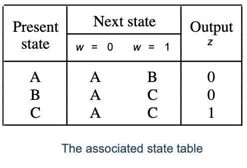
| Present state | Next state () | Next state () | Output |
|---|---|---|---|
| A | A | B | 0 |
| B | A | C | 0 |
| C | A | C | 1 |
Reading: from state A with input , the next state is A and the output is . From state C with , the next state is C and the output is .
The output column appears once per row in a Moore-style table because output depends only on state. For Mealy, you’d have a separate output column per input value.
How to use it
Three things flow from a state table:
-
Minimize states. Two states with identical behavior (same outputs, same transitions) can be merged. See State Reduction.
-
Assign binary codes to states. Pick how many bits to use and what code each state gets. See State Assignment.
-
Derive logic. With states encoded as bit patterns, the state table becomes a truth table for the next-state and output functions. From there, Karnaugh Map or VHDL synthesis produces the gate-level circuit.
The state table is the natural input form for synthesis tools. Often you write the design as a VHDL case statement, which is a state table in code, and the tool handles the rest.