A voltage doubler is a diode–capacitor circuit whose DC output is about twice the peak of the AC input. Cascade a Clamper circuit with a Peak rectifier: the clamper offsets the waveform so its excursion reaches , and the peak rectifier captures that doubled peak.
How the two stages combine
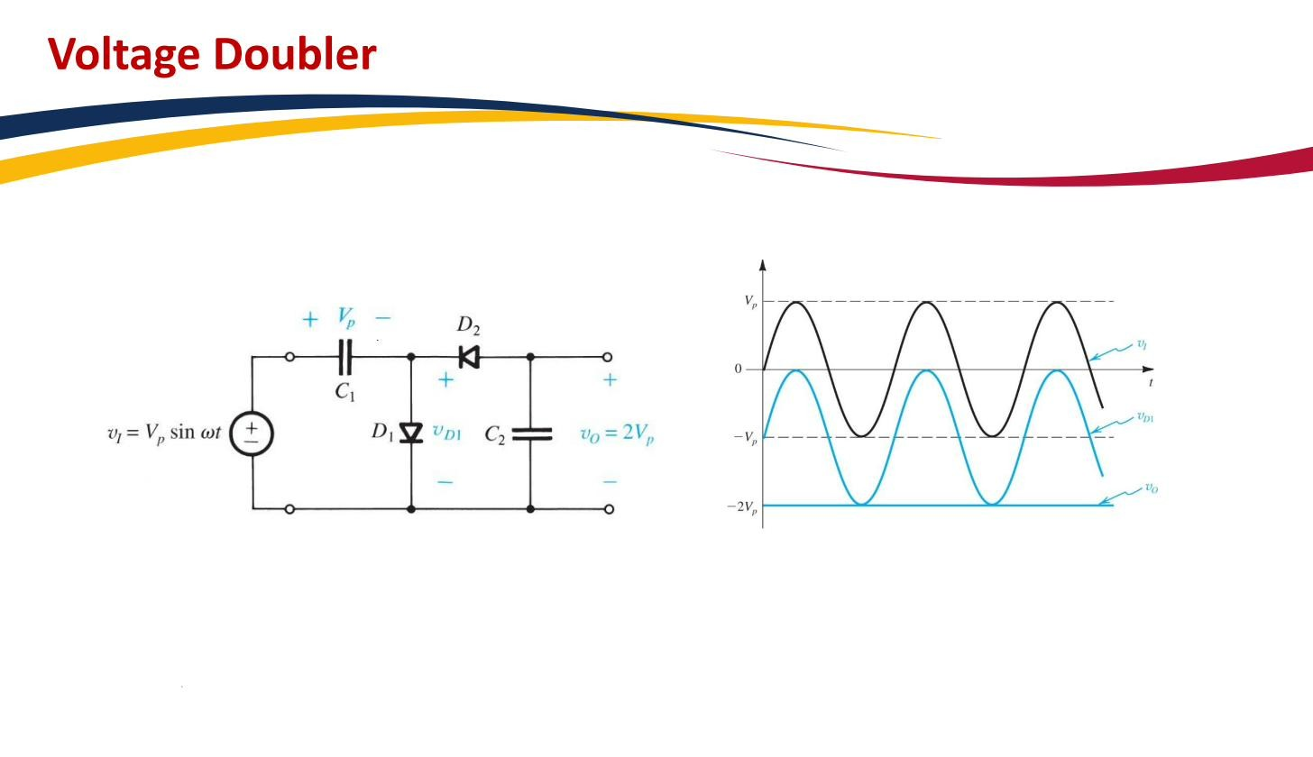
Stage 1 — clamper ( + ). The clamper shifts the AC input so that its negative peak sits at 0 V. An input that swung from to (peak-to-peak ) slides up by , so it now swings from 0 to . Same waveform shape, just a shifted DC level, so its peak is now instead of .
Stage 2 — peak rectifier ( + ). Fed with the clamped waveform whose peak is , the peak rectifier charges up to that peak and holds it there. The output is therefore a DC voltage of magnitude (minus the two diode drops, so really with the Constant-voltage-drop model).
 A clamper stage followed by a peak rectifier; output magnitude ≈ .
On polarity: with the diode orientation drawn here the output settles at about (minus the diode drops); reversing both diodes gives the more common version. Magnitude is twice the input peak either way, only the sign depends on diode direction.
Why you would want one
A voltage doubler gives a DC voltage higher than the rectified AC peak available to you, without a bigger transformer. A common use: generating the higher bias rail a small LCD backlight needs from a 5 V USB rail. Stacking more clamper/peak-rectifier stages gives a voltage multiplier (tripler, quadrupler, …), each stage adding another to the output; the Cockcroft–Walton ladder used for high-voltage generation is the same trick repeated. The price of multiplying is poor current capability: each stage’s capacitors must supply the load through a long chain, so doublers and multipliers are for low-current, high-voltage needs, not power delivery.