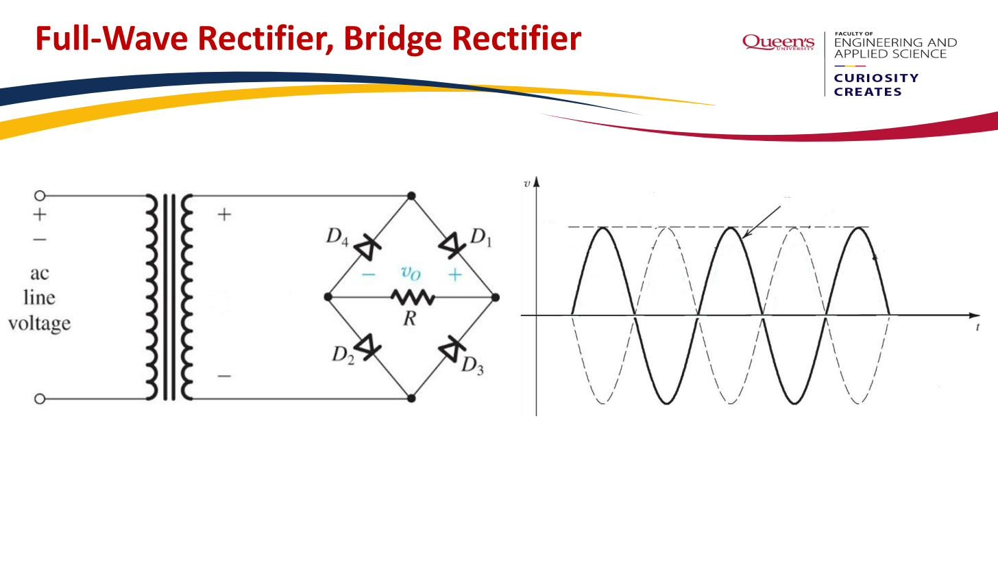
The bridge rectifier is a Full-wave rectifier built from four diodes arranged in a diamond around the load, fed from a single transformer secondary (no centre tap). On each half-cycle two diagonally-opposite diodes conduct, always pushing current through the load in the same direction.
How the four diodes work
Picture the four diodes as a diamond with the AC source connected to the left and right corners and the load connected across the top and bottom corners.
- Positive half-cycle (left corner positive): current flows from the source, through one diode into the top of the load, down through the load, out of the bottom, and back through a second (diagonally opposite) diode to the source. The other two diodes are reverse biased and off.
- Negative half-cycle (right corner positive): the other diagonal pair conducts. The path is arranged so the current still flows the same way through the load, top to bottom, even though the source polarity reversed.
So the load always sees current in one direction: full-wave rectification, output frequency twice the input, no gaps.
 Four diodes in a diamond; two conduct diagonally each half-cycle, current always one way through the load.
Advantages over the centre-tapped version
The whole transformer secondary is active on every half-cycle (no idle half-winding), so the bridge uses the transformer copper more efficiently than the Center-tapped full-wave rectifier, and it needs no centre tap.
Its Peak inverse voltage is only , about half the that each diode in a centre-tapped rectifier must withstand. The off diodes in a bridge are protected by the conducting diodes, so no single diode sees more than one peak.
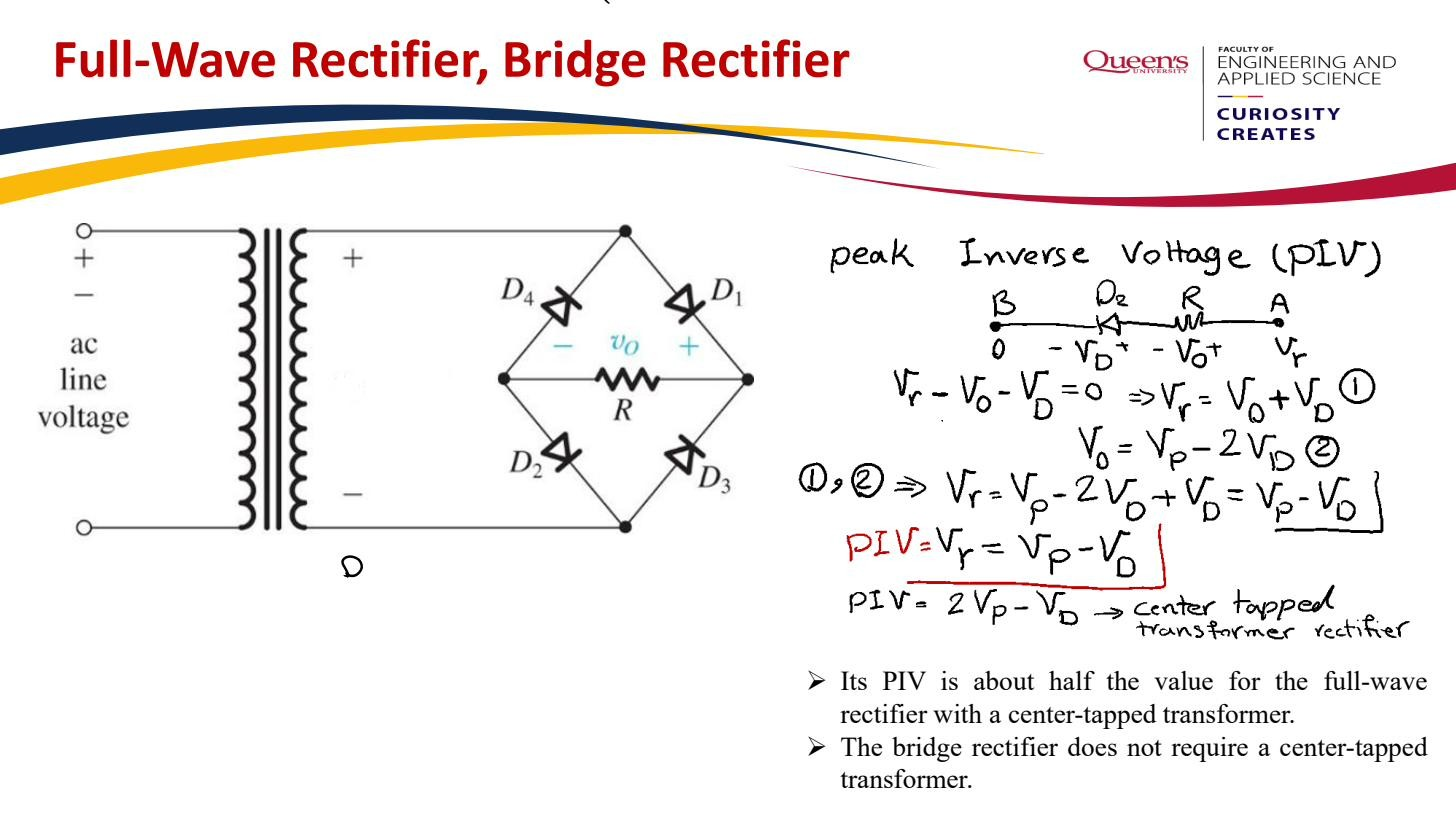 Bridge PIV , ~half the centre-tapped value, and needs no centre tap.
The cost: two diode drops
The price is that the conduction path always goes through two diodes in series, not one. With the Constant-voltage-drop model each drops V, so the peak output is
instead of the of a single-diode-path rectifier.
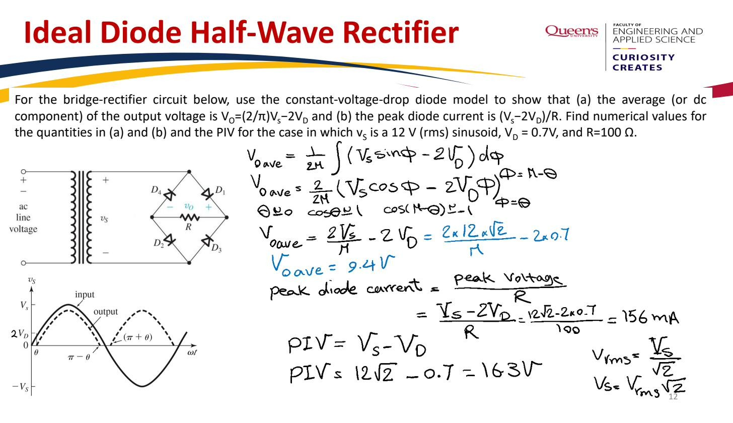 CVD worked example: two series diode drops cost ~1.4 V from the peak output.
Worked example. Secondary peak V, V. Peak output is V. The two diode drops cost about V: negligible at high voltages but a big fraction of a low-voltage supply, which is when a centre-tapped or active arrangement may be preferred. At mains-level voltages the bridge’s lower PIV and better transformer use win, so it’s the most common rectifier in practice.