A rectifier is a diode circuit that converts an alternating-current (AC) input into a unipolar output, one that is always positive (or always negative). It’s the first step in turning wall-socket AC into the DC that electronics run on, so the rectifier is the front end of every DC power supply.
Why it is needed
The wall socket delivers a sinusoid that swings symmetrically positive and negative; its average value is zero. Almost every circuit needs a steady DC rail, and you can’t get DC out of a zero-average waveform by averaging it. You first have to make it one-sided. The Diode’s one-way-valve behaviour does exactly that: pass one polarity, block the other. The result is a lumpy but unipolar waveform that a smoothing capacitor averages into something close to DC, which a Zener voltage regulator or active regulator can then clean up further.
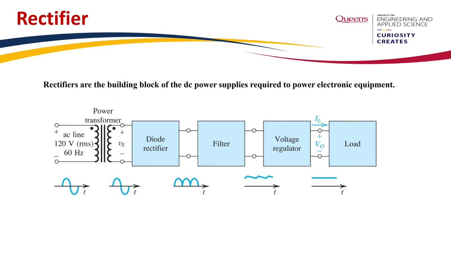 Rectifiers are the building block of the DC power supplies that power electronic equipment.
The three families
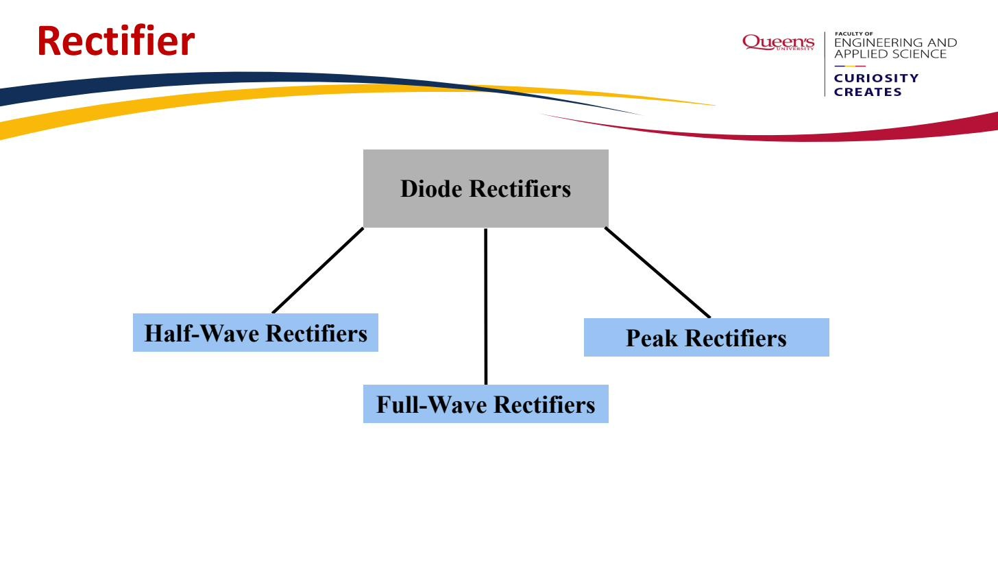 Three families: half-wave, full-wave (centre-tapped or bridge), and peak rectifier with a smoothing capacitor.
- Half-wave rectifier — a single diode in series with the load. Passes only one polarity’s half-cycles, throws the other half away. Simplest, but wasteful and very lumpy.
- Full-wave rectifier — uses both half-cycles by flipping the negative ones upright. Two standard topologies: the Center-tapped full-wave rectifier (centre-tapped transformer, two diodes) and the Bridge rectifier (single secondary, four diodes). Output frequency is twice the input.
- Peak rectifier — any of the above with a smoothing capacitor across the load. The capacitor holds the voltage near the peak between conduction bursts, giving approximately DC with a small Ripple voltage.
These aren’t separate devices, just arrangements of diodes around a load. Which one you pick trades off diode count, transformer cost, Peak inverse voltage rating, and output smoothness.