A diode is a two-terminal device made from a single PN junction. One-way valve: current flows readily in the forward direction once a small voltage is applied, and essentially no current flows in reverse. Rectifiers, limiters, clampers, voltage multipliers, voltage references are all consequences of that asymmetry.
Terminals and symbol
The two terminals are the anode (the p-side of the junction) and the cathode (the n-side). The schematic symbol is a triangle (the anode) pointing into a bar (the cathode). The triangle is an arrowhead pointing in the direction of conventional current flow when the diode conducts: from anode to cathode, p to n. The bar marks where the arrow stops; current does not flow backwards through it.
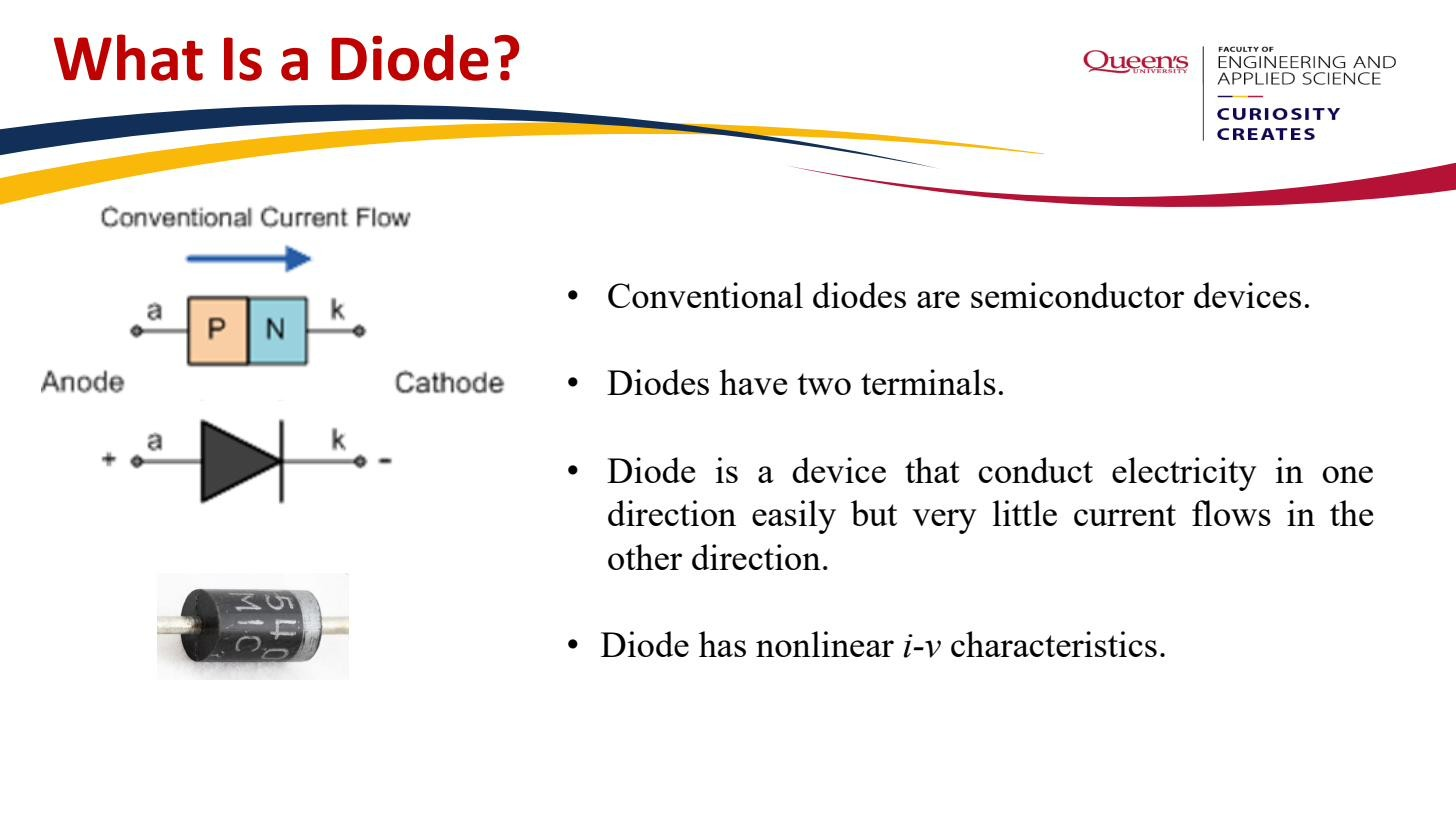 A diode: current flows easily anode(p)→cathode(n), blocked in reverse.
Mnemonic: the symbol looks like an arrow that can only fire one way.
Biasing: forward vs reverse
Biasing means applying a DC voltage across the device. Two cases, mapping directly onto the PN junction physics.
Forward bias puts the anode positive relative to the cathode. This voltage opposes the junction’s built-in barrier, lowering it, so current grows exponentially with the applied voltage, quantified by the Diode equation. Since that current is exponential and unbounded, a forward-biased diode is never used by itself: it’s non-linear and would draw unlimited current and destroy itself, so you always need a series resistor (or some other current-limiting element).
Reverse bias puts the cathode positive relative to the anode. This adds to the built-in barrier, raising it, and the diode is essentially an open circuit. Only a tiny Reverse saturation current leaks through, carried by minority carriers.
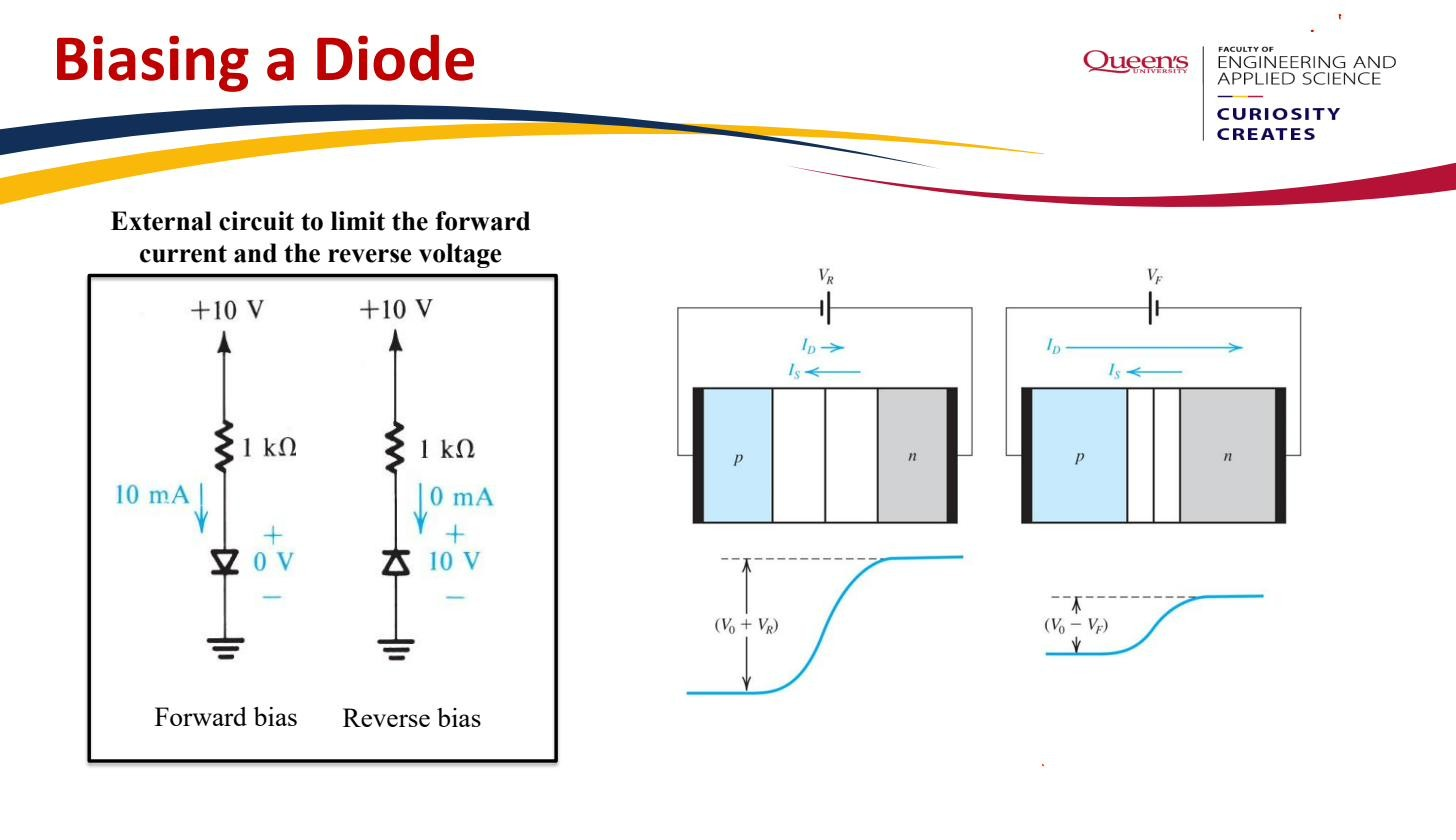 Forward bias passes current, reverse blocks; a series resistor is essential to limit the forward current.
The four models
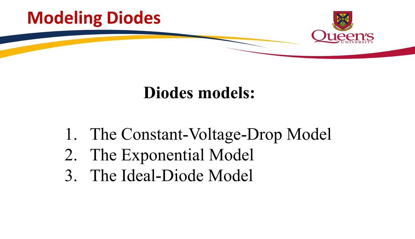
The diode’s true – relation is exponential and exact (within the physics), but solving a circuit with an exponential means solving a transcendental equation by hand. So we keep a hierarchy of approximations and pick the simplest one that gives an acceptable answer:
- Ideal diode model — a perfect switch. Short circuit when forward biased, open circuit when reverse biased, zero threshold. Use it when the circuit voltages are much larger than 0.7 V so the diode drop is negligible.
- Constant-voltage-drop model — when on, the diode is a fixed V battery; when off, an open circuit. By far the most-used model in this course.
- Exponential diode model — the full Diode equation . Most accurate, but combined with KVL it gives a transcendental equation solved by Iterative diode analysis.
- Diode small-signal resistance — the fourth model. For a small time-varying signal riding on a DC bias, the diode looks like a linear resistor equal to the inverse slope of the exponential at the Operating point.
 Three tractable models: ideal, constant-voltage-drop, exponential. The small-signal model is the fourth.
The first three are large-signal models used for DC analysis; the fourth is the small-signal model used once the DC operating point is known. They’re not competitors: you use a large-signal model to find the bias point, then the small-signal model to find what the signal does.