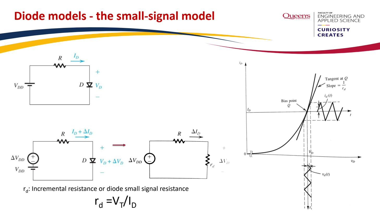
The diode small-signal resistance is the effective linear resistance a forward-biased Diode presents to a small time-varying signal riding on top of a DC bias. It’s the inverse of the slope of the Diode equation evaluated at the Operating point: the fourth diode model, used once the DC bias is known and you want to know what the signal does.
Derivation
The diode is non-linear, so it has no single “resistance”. But over a small enough voltage swing the exponential – curve looks locally straight, and a straight – line is a resistor. The slope we want is the derivative of the Diode equation with respect to :
The last step uses itself, which is the trick: the slope is just the current divided by the Thermal voltage. Evaluate this at the DC operating point, where . The small-signal resistance is the inverse of that slope (resistance is , conductance is ):
mV is the Thermal voltage and is the DC bias current set by the Operating point. Notice depends only on the bias current and temperature, not on or the device area. (Strictly with the diode ideality factor ; the convention used throughout this course reduces it to .) This is the diode analogue of the BJT’s .
 depends only on DC bias current and thermal voltage.
Numbers and intuition
At mA: . At µA: .
The smaller the bias current, the larger . Intuition: at high the exponential is rising steeply, so a tiny voltage wiggle causes a big current wiggle, low resistance. At low the curve is flatter, so the same voltage wiggle barely moves the current, high resistance. The validity condition is that the signal swing must be much smaller than (~25 mV), because the linear approximation comes from truncating the Taylor expansion of the exponential. See Linearisation around an operating point.
Worked example: signal across a single diode
A small AC source is in series with a 10 k resistor and a forward-biased diode powered by a V supply. Find the AC voltage across the diode.
Step 1 — DC (find the bias). Zero the AC source. KVL: . Using the Constant-voltage-drop model for the DC part, V, so
Step 2 — AC (use ). Zero the DC supply (short it). The diode becomes the resistor . The signal source now sees a simple voltage divider made of in series with :
So a small input signal produces a tiny AC voltage across the diode, attenuated by . If has, say, a 1 V amplitude, then mV, comfortably less than mV, so the small-signal approximation was justified.
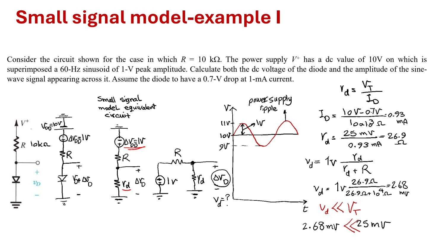 With V, kΩ, mA ⇒ ; a divider sets mV , so the small-signal approximation holds.
DC bias first, then AC with the device replaced by its small-signal element: that’s the general Small-signal analysis procedure, here on its simplest device.