A Zener diode is a Diode built to undergo Reverse breakdown at a controlled voltage and operate safely in that region. While in breakdown its terminal voltage is almost independent of the current: change the current by a factor of ten and the voltage moves only a few percent. That near-constant voltage is what the Zener voltage regulator and the diode Voltage reference run on.
How it is used
A Zener always runs reverse biased. The breakdown polarity is the working polarity, so the symbol and orientation are drawn with the operating current flowing cathode-to-anode (opposite of an ordinary diode). It needs a series current-limiting resistor; the resistor sets the current and keeps power dissipation within the safe limit. Below the breakdown voltage it behaves like an ordinary reverse-biased diode (open circuit); above it, it clamps to .
Which mechanism, and why ~5–6 V is special
Breakdown happens by one of two mechanisms (detailed in Reverse breakdown): the Zener effect, field-driven tunnelling, dominates below about , while avalanche multiplication dominates above about . The two have opposite temperature coefficients: the Zener effect gives a negative tempco, avalanche a positive one. Around – they roughly cancel, so a Zener rated there drifts least with temperature. That’s why precision references cluster near , not because that voltage is otherwise special. (Despite the name, most “Zener” diodes above ~6 V actually break down by avalanche.)
Datasheet parameters
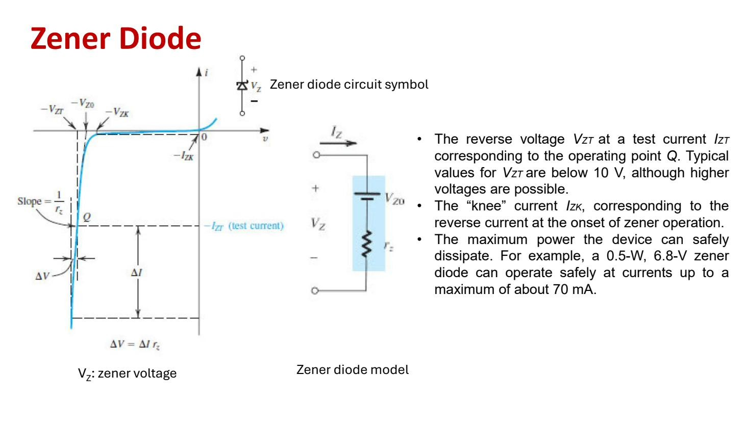 Zener parameters: at test current , knee , power-limited max current; linearised model .
- — rated breakdown voltage, specified at a particular test current . Since the voltage drifts slightly with current, you have to say where you measured it. Commercial Zeners span roughly to ; the common parts sit in the few-volt to tens-of-volts range.
- — the test current at which is quoted.
- — knee current, the current at the onset of breakdown, the bottom of the curve where the breakdown bend is. Below the device isn’t properly in breakdown and regulation is poor, so keep the current above .
- Maximum current — set by safe power dissipation. For a 0.5 W, 6.8 V Zener the max current is about mA. Exceed it and the device overheats and fails.
Linearised model
For hand analysis the breakdown region is modelled as a straight line: an ideal source in series with a small dynamic resistance . is the voltage-axis intercept you get by extrapolating the steep breakdown line back to zero current. It’s not the same as , which is the voltage at a real operating current. is the Zener dynamic resistance, the slope of the breakdown line: . A small means the line is nearly vertical, so the voltage barely changes with current. That’s what makes a good regulator.
The Zener in breakdown is usually treated by its DC value alone; the refinement comes in only when you need to predict how much the regulated voltage moves under load. That voltage-source behaviour feeds into the Zener voltage regulator.