The standard board-level Common-source amplifier: a voltage-divider-biased MOSFET wrapped in the resistors and capacitors needed to bias it reliably and amplify AC signals. Biasing, gain, and Amplifier frequency response all show up in the one circuit.
 Voltage-divider bias, source resistor, coupling caps, optional source bypass.
The components and what each one does
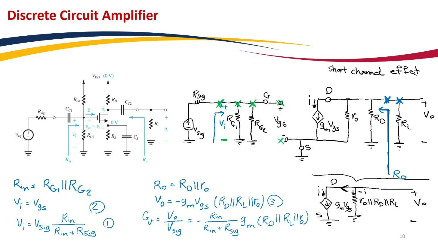
- Voltage-divider gate bias (): sets the fixed gate reference . The gate draws no current (Gate oxide), so these can be megohms, keeping input resistance high. See Voltage-divider bias.
- Source resistor : DC Negative feedback, so the operating point is set by resistors, not the spread-prone / (). The MOSFET biasing backbone.
- Drain resistor : converts the signal drain current into output voltage swing. Gain is ; also sets how far the output can swing.
- Input coupling capacitor (signal source → gate): blocks DC, passes AC. Keeps the source’s DC level from disturbing while letting the AC signal through. See Coupling capacitor.
- Output coupling capacitor (drain → load): blocks the drain’s DC bias from reaching the load, passes the amplified AC.
- Source bypass capacitor (across , optional): shorts for AC so the full gain comes back, while leaving in place for DC so the bias stabilisation survives. Without it the stage has Source degeneration (lower gain, but more stable); with it, full gain.
Why this is the canonical circuit
It separates two jobs that fight each other. DC: you want in the source for a stable operating point. AC: you want gone, because it kills gain. The bypass cap does both, DC-open (keeps ), AC-short (removes it). The coupling caps isolate the DC bias of each stage from its neighbours so each biases independently.
These reactive elements bring in frequency dependence: at low frequencies the coupling and bypass caps stop acting as short circuits and the gain falls off. That’s the low-frequency end of the Amplifier frequency response. Sizing the caps so their corners sit well below the band of interest (e.g. ≪ 20 Hz for audio) is the next design step.