A lookup table (LUT) is a memory that implements an arbitrary Boolean function by storing its truth-table outputs. With inputs and output, a LUT stores bits, one bit per input combination, and the inputs index into this memory to retrieve the output.
A 3-input LUT stores bits; a 4-input LUT stores ; a 6-input (typical in modern FPGAs) stores .
Because every function of inputs has a unique truth table of entries, an -input LUT can implement any Boolean function of variables. You don’t pick a function and then design gates; you write the truth table directly into LUT memory.
Building larger functions
Real designs need more than 3 or 6 inputs. The synthesis tool decomposes a large function into pieces small enough to fit in a single LUT, then chains LUTs together using the FPGA’s routing.
Worked example: implement on an FPGA with 3-input LUTs.
Each AND term takes one 3-input LUT (storing the truth table for that AND). A fourth 3-input LUT then ORs the three results. Total: four 3-input LUTs.
Or with smaller LUTs (2-input), it takes more pieces. For :
- LUT 1: (truth table: 0,0,0,1)
- LUT 2: (0,0,0,1)
- LUT 3: (0,0,0,1)
- LUT 4: (0,1,1,1)
- LUT 5:
Five 2-input LUTs.
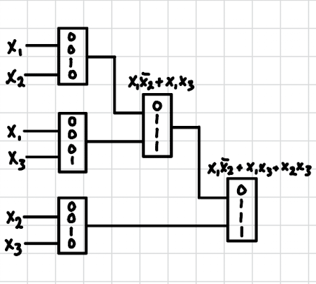
Notice the truth tables of are the same (they all implement AND), but the inputs they’re connected to differ. That’s how distinct functions get realized from identical LUT contents.
There’s a depth penalty too. The chain followed by is 3 LUTs deep, so every signal travels through three LUT delays. The same function in a single 3-input LUT (storing the full majority truth table) is one LUT deep. Smaller LUTs cost depth as well as count, and depth dominates clock-period limits in synthesizable designs. This is why FPGAs evolved from 4-input LUTs (Xilinx Virtex era) to 6-input LUTs (Virtex-5 onwards): wider LUTs let synthesis pack more logic per level.
Mental model
Think of a LUT as a hash table from input bit patterns to output bits:
# XOR as a 2-input LUT
lut = {
    (0, 0): 0,
    (0, 1): 1,
    (1, 0): 1,
    (1, 1): 0,
}
# Looking up (1, 0) gives 1 — exactly what XOR returns.
In silicon the implementation is a small SRAM with a multiplexer: the input bits drive the multiplexer’s select lines, picking out the stored output bit. The LUT memory is loaded as part of the FPGA’s configuration bitstream when it powers up.
LUTs are why Multilevel synthesis matters in FPGA design: a function decomposed into smaller-fan-in pieces fits more naturally into the LUT structure than a single huge SOP that wouldn’t fit any LUT.