The input offset voltage is the small DC voltage (a few millivolts) that a real op-amp effectively has between its inputs even when nothing is applied. Tie both inputs together (zero differential input) and the output is not zero. Model this as a tiny DC source in series with one input that the op-amp then amplifies along with everything else. It is a real op-amp imperfection; the ideal model says it is zero.
It arises from unavoidable mismatch in the op-amp’s internal input transistor pair (geometry, threshold, differences from manufacturing). The op-amp cannot tell apart from a real signal, so it treats it like one.
It gets the full closed-loop gain
appears at the input, so it is multiplied by exactly the same Closed-loop gain as the wanted signal. Treat as a DC input to a non-inverting-style gain (the gain a signal injected at the input sees, regardless of whether the circuit is the inverting or non-inverting topology):
This is a DC error at the output even with zero input. Plug in numbers: a amplifier () with produces a standing output offset of . For a precision DC measurement that may be far larger than the quantity you are trying to measure, so the reading is meaningless. And that DC pedestal eats into the available swing, pushing a high-gain stage toward Op-amp output saturation and clipping or burying a small AC signal sitting on top of it.
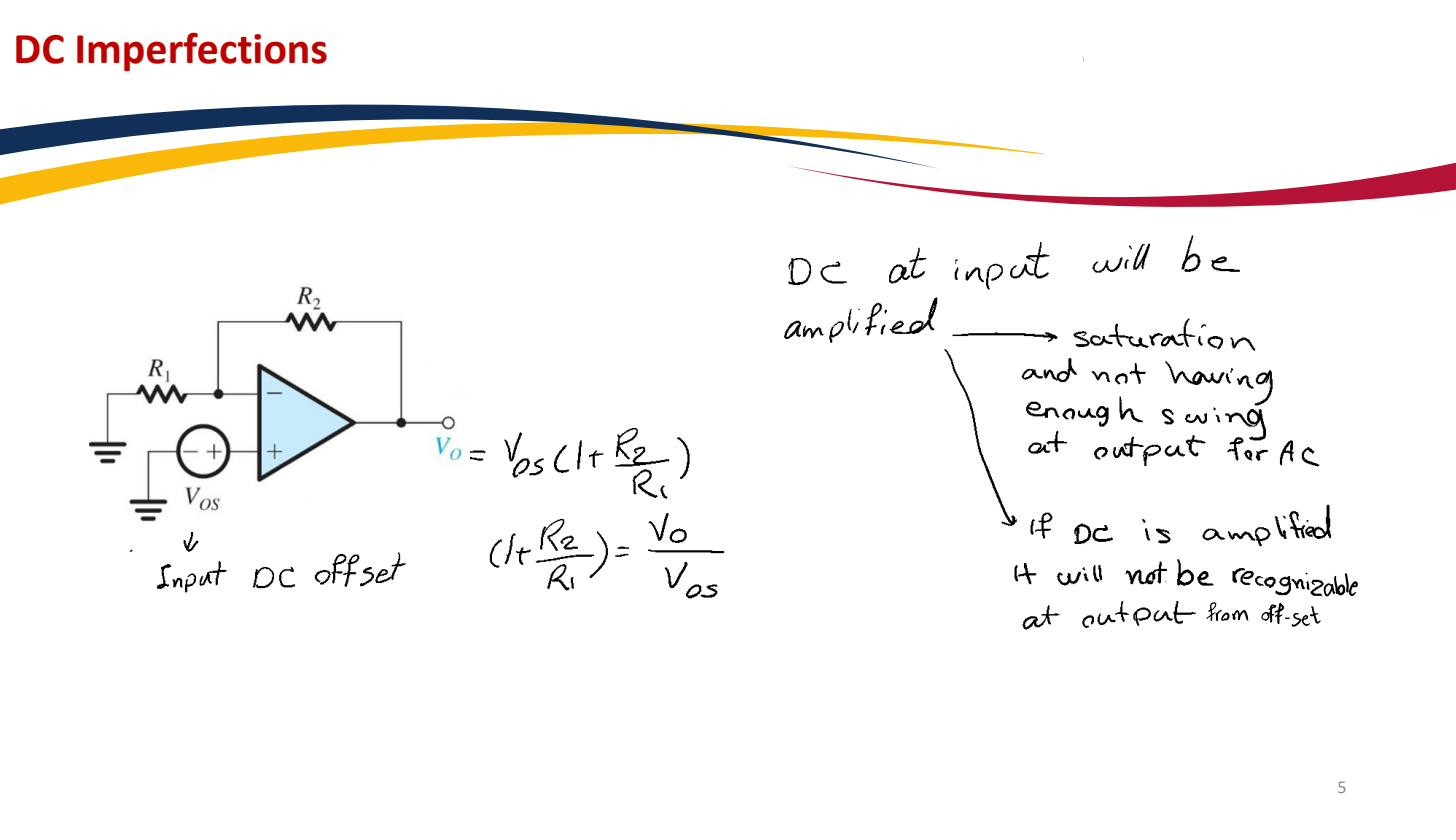 amplified by gives an output DC error even with zero input.
When precision is required, is nulled externally — many op-amps provide offset-null pins for a trim potentiometer, or the offset is removed downstream by AC coupling or digital calibration. For AC signals well above DC, a series blocking capacitor simply discards the amplified DC offset. The companion DC imperfection, where input currents rather than a voltage cause the error, is the Input bias current.