An op-amp integrator (Miller integrator) is the inverting configuration with the feedback resistor replaced by a capacitor. Its output is the running time-integral of the input, scaled and inverted:
Derivation
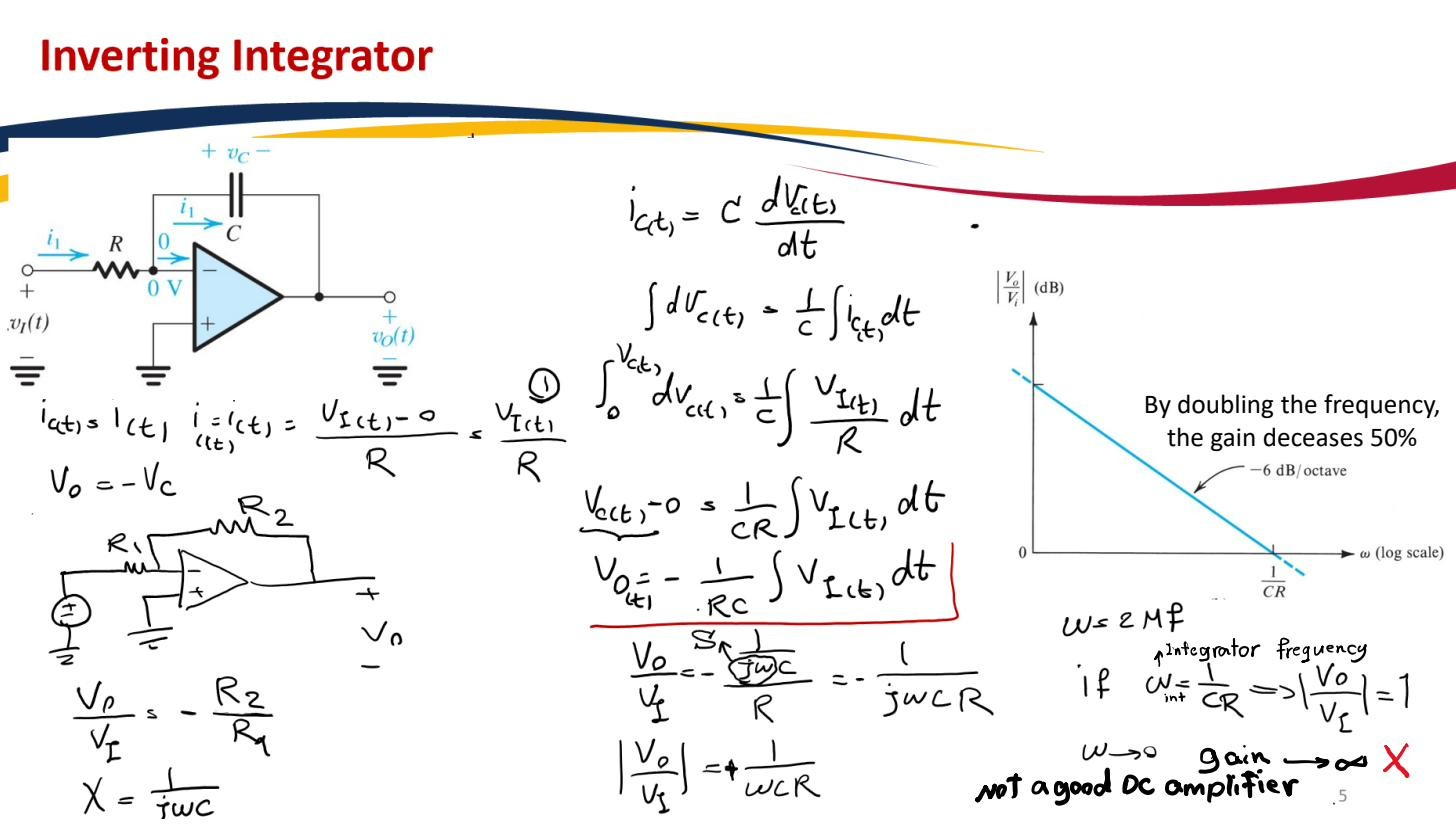
Keep the input resistor ; replace the feedback element with a capacitor from the inverting node to the output. Ground the non-inverting input.
Golden rule 2 of the Ideal op-amp model makes the inverting node a virtual ground: . The current drawn from the source through is therefore
Golden rule 1 says none of this current enters the op-amp, so all of it flows into the capacitor: . The capacitor’s voltage is the voltage across it; one plate is at the virtual ground () and the other is at , so . The defining law of a capacitor is , so
Set :
Solve for by integrating both sides with respect to time:
The constant is the integration time constant. A constant input produces a ramp output , the textbook signature of integration.
 Feedback resistor replaced by ⇒ gain ∝ 1/frequency (integration).
 Output = time integral of input scaled by .
Frequency-domain view
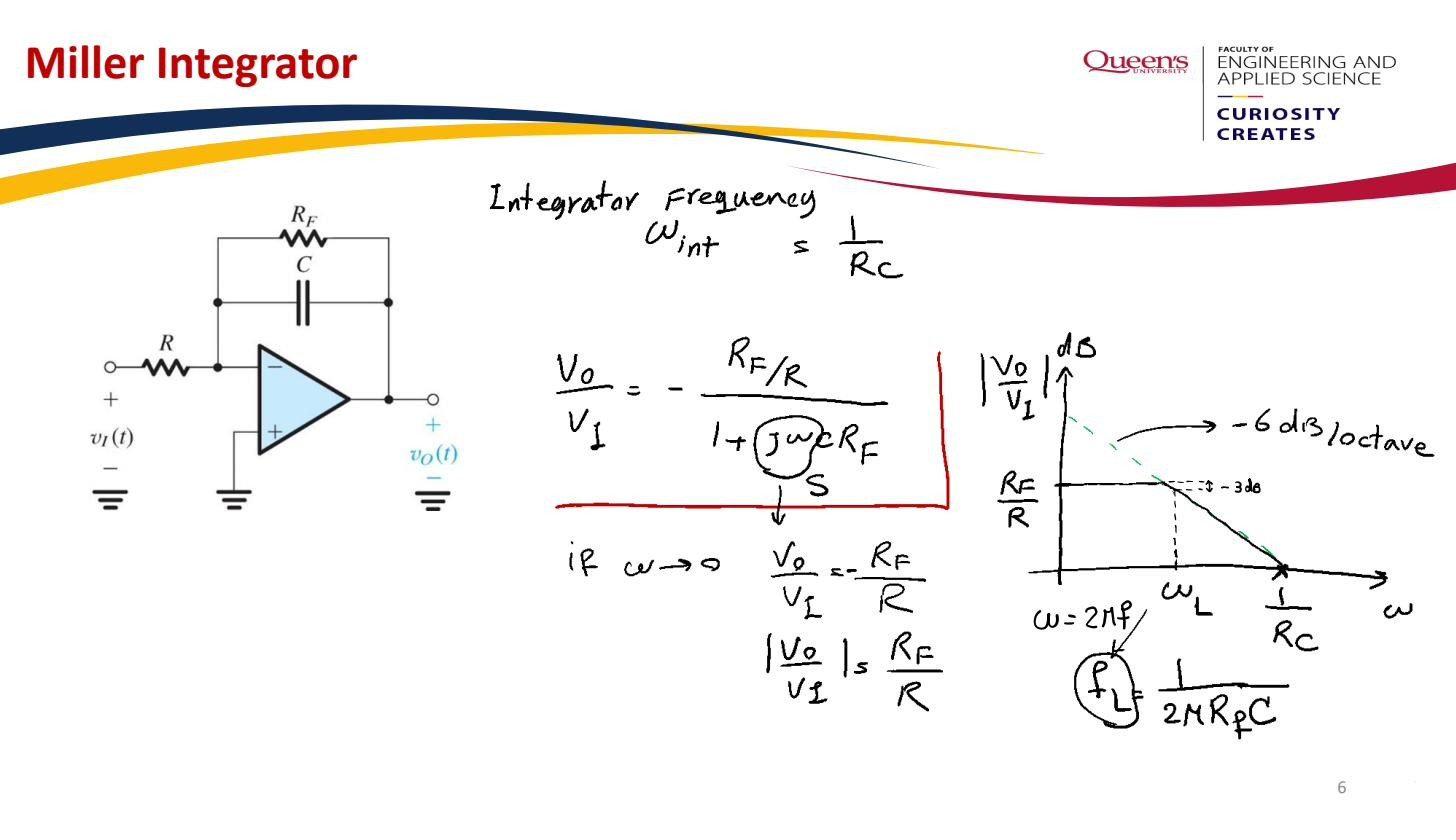
Replace by its impedance and treat it as the feedback element in the inverting gain formula :
The magnitude is . It falls with frequency at (doubling halves the gain), the Bode plot signature of integration ( is the frequency-domain integral operator). Low frequencies are amplified hugely; high frequencies are attenuated.
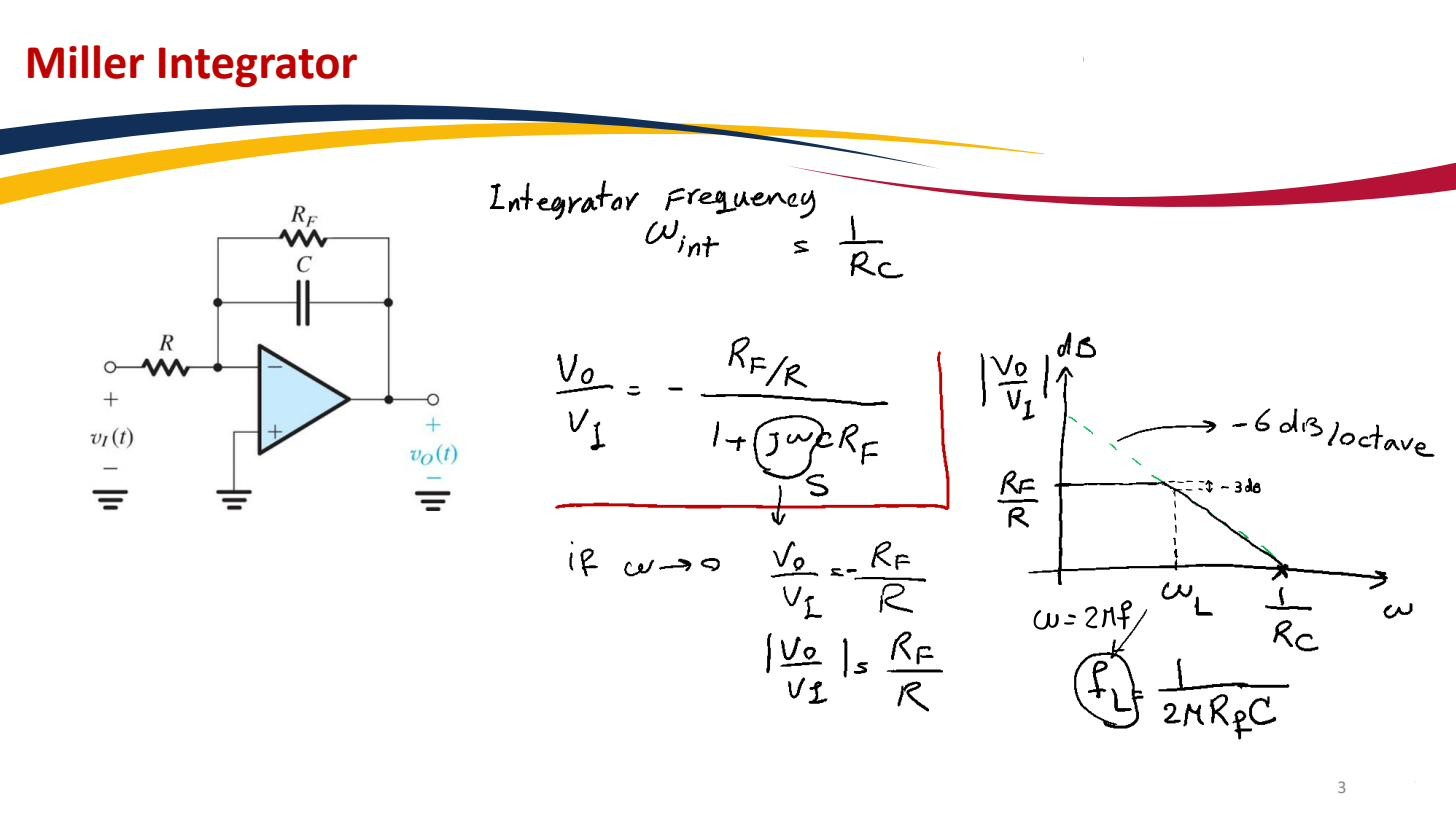 Magnitude −20 dB/decade; infinite ideal DC gain ⇒ a parallel for DC stabilisation.
The DC-saturation hazard
Set in and the gain goes to infinity: the ideal integrator has infinite DC gain. That’s dangerous in practice. Any tiny DC Input offset voltage at the input is integrated forever and ramps the output into the rail (Op-amp output saturation) given enough time. Real integrators always place a large resistor in parallel with . caps the DC gain at the finite (but large) value while leaving the integrating behaviour intact above the corner . Swapping which element is the capacitor gives the Op-amp differentiator.