The T-model is the BJT small-signal model rearranged so that the resistance between base and emitter is the [[Emitter resistance|]] instead of . Fully equivalent to the BJT hybrid-pi model (same device, same answers), but its topology makes circuits where the emitter is the signal node much easier to analyse.
Its elements:
- A resistance between base and emitter, carrying the full emitter current . Recall at 1 mA, much smaller than , because the emitter sees the full current while the base sees only .
- A controlled current source between collector and emitter, (equivalently ). Since and , , the same current as in the hybrid-π, just written in terms of .
- An optional in parallel for the Early effect.
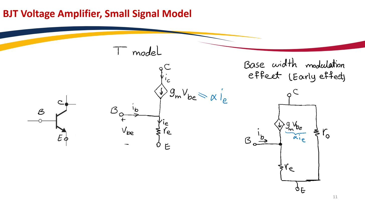 T-model: between base and emitter, controlled source collector-to-emitter; add in parallel for the Early effect. Equivalent to the hybrid-π but more convenient when the emitter is the signal node.
The shape (named for the “T” the resistor and the two branches make) puts directly in the signal path when you feed the emitter. So it’s the natural model for the Common-base amplifier (input at the emitter, input resistance falls straight out as ) and the Emitter follower (output taken at the emitter, output resistance ≈ drops out cleanly). It also makes the Resistance reflection rule obvious: a resistor in the emitter is in series with the full , while the base only carries , so that resistor looks times larger from the base. Use the hybrid-π when the base is the input (common-emitter), the T-model when the emitter is.