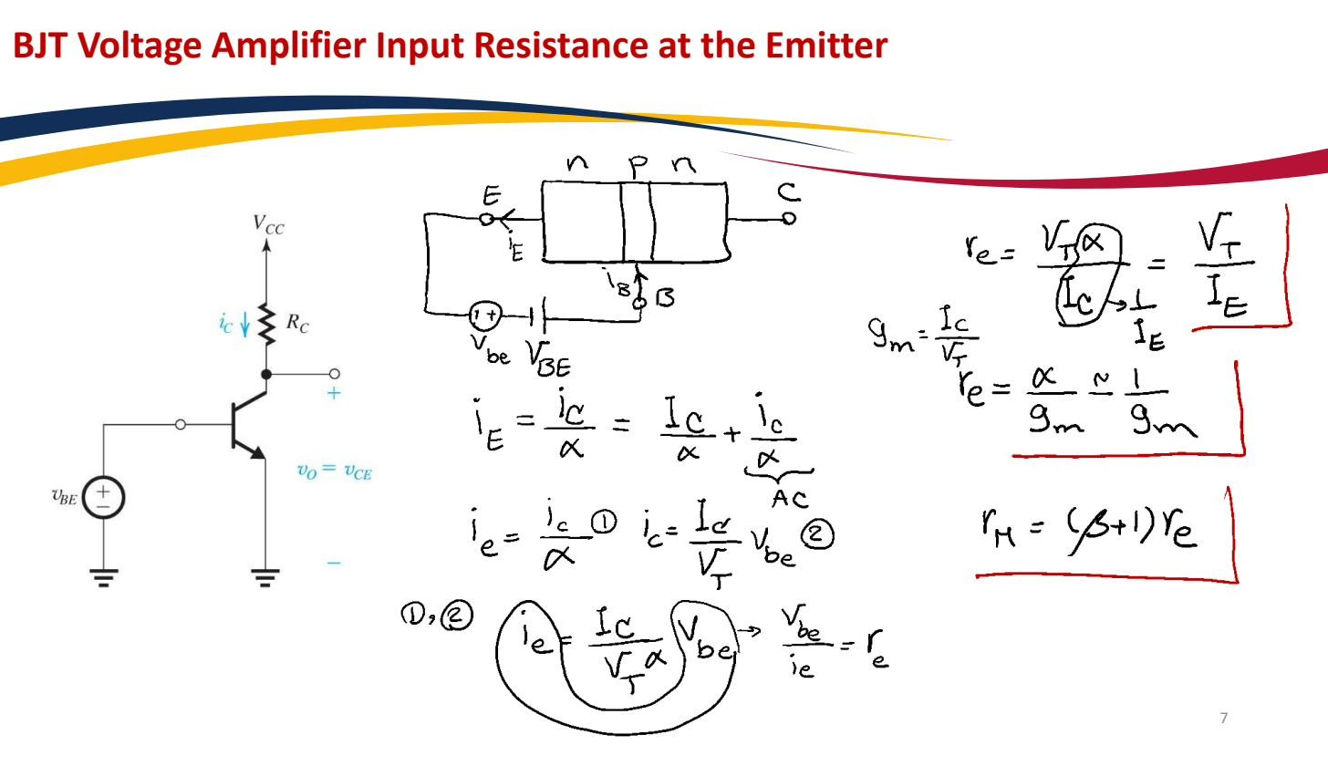
The emitter resistance is the small-signal resistance seen looking into the emitter of a BJT (base held at AC ground, signal applied to the emitter):
The approximation uses , which holds for any reasonable (they differ by the factor ). More precisely . It is the intrinsic emitter resistance of the device, not a physical resistor you add but the small-signal resistance the emitter terminal presents.
 Resistance at the emitter: at , much smaller than . This is what the common-base configuration exploits.
Why it is β times smaller than r_π
The input resistance at the base is at 1 mA; the emitter resistance is at the same bias, a factor of smaller. The reason is which current flows through the controlling node:
- Drive the base: the base only carries . The same voltage produces a tiny current, so the resistance looks large: .
- Drive the emitter: the emitter carries the full current (β times bigger than ). The same now produces a large current, so the resistance looks small: .
Same junction, same , but the emitter node sees β-times-more current than the base node, hence β-times-less resistance. Formally , the Resistance reflection rule in its purest form. Numerically, at , : .
This very low emitter resistance is exactly what the Common-base amplifier exploits (its input resistance is just , tens of ohms) and why an Emitter follower has such a low output resistance (≈ ). is the base–emitter element of the T-model form of the BJT small-signal model, the representation that is convenient whenever the emitter is the signal node.