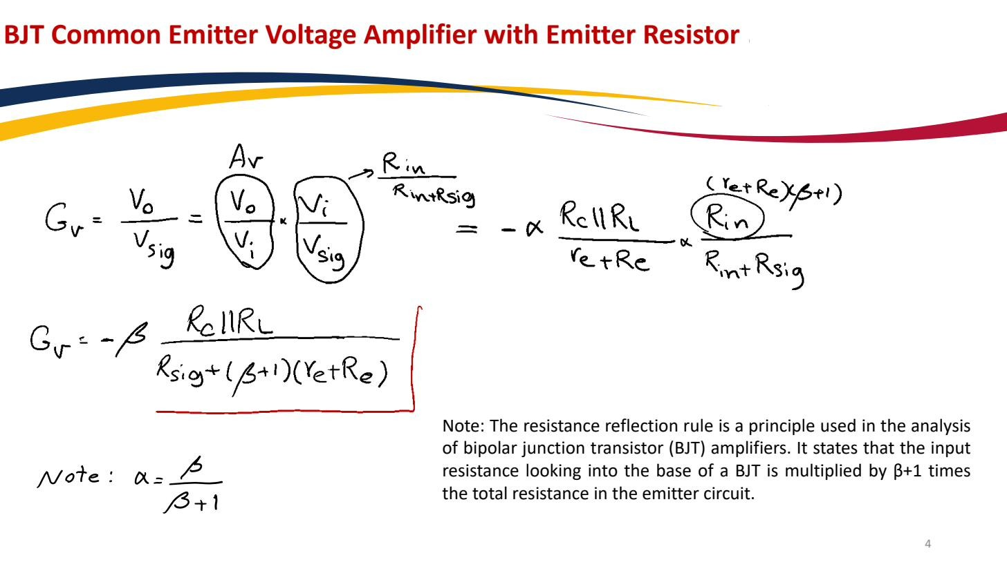
A resistance moved across the base–emitter “boundary” of a BJT changes by a factor of . This is the intuition that makes BJT amplifier analysis fast.
- A resistance in the emitter is seen from the base as , bigger.
- A resistance in the base is seen from the emitter as , smaller.
 A resistance in the emitter looks times larger when viewed from the base.
Why the factor is (β+1)
It comes from the current ratio between the two terminals. By KCL and the definition of β, : the emitter carries times the base current.
Put a resistor in the emitter lead. The voltage across it is set by the emitter current, . Viewed from the base, that same voltage is produced by the much smaller base current . The apparent resistance is voltage divided by the base current:
Same voltage drop, but measured against a smaller current, so it looks more resistive. Going the other way (a base resistor seen from the emitter) the larger emitter current measures the same voltage, so the resistance looks times smaller. The cleanest special case is the device’s own [[Emitter resistance|]]: , so the BJT input resistance is the intrinsic emitter resistance reflected to the base. The BJT T-model makes this visually obvious.
For large the factor , so some textbooks state the rule with just . At this level the exact factor is ; use it.
Where it shows up
This rule is everywhere in BJT amplifier work.
- Emitter degeneration: an un-bypassed in the emitter raises the input resistance of a Common-emitter amplifier to , the reflected to the base.
- Emitter follower: the high input resistance is the load resistance on the emitter reflected up to the base, which is why the emitter follower is such a good Buffer amplifier.
- Working down from base to emitter explains the emitter follower’s low output resistance: the source resistance at the base reflects down by .