The hybrid-π model is the most common form of the BJT small-signal model. It represents an active-mode BJT as three elements between its base, emitter, and collector terminals:
-
An input resistance between base and emitter, the BJT input resistance, . This is where the small-signal base current flows, and the controlling voltage appears across it.
-
A controlled current source between collector and emitter for the amplifying action. Two equivalent expressions:
- a voltage-controlled current source (controlled by the voltage across ), or
- a current-controlled current source (controlled by the current through ).
Same source either way: since and , .
-
An optional output resistance in parallel with the source, collector to emitter. Include it only when the Early effect matters (computing maximum gain or output resistance).
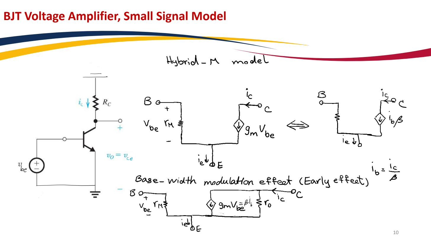 The hybrid-π model in its two equivalent forms: a VCCS (left) or a CCCS (right); both have between base and emitter. The bottom panel adds between collector and emitter for the Early effect.
Reach for the hybrid-π whenever the base is the input node, since sits right there as the input resistance. That’s the Common-emitter amplifier and Emitter follower case. When the signal drives the emitter instead (common-base, emitter-follower output resistance), the algebra is cleaner with the BJT T-model, which is the same model rearranged so rather than sits between base and emitter. Both forms are interchangeable and give the same numerical answer.