The MOSFET transfer characteristic is the plot of drain current versus gate-source voltage at a fixed (device in saturation). It says how the input voltage controls the output current, which is the relationship an amplifier runs on.
Shape of the curve
Two pieces:
- Below threshold (): no channel, so . The curve sits flat on the axis. This is the MOSFET cut-off region.
- Above threshold (): the square-law takes over,
so the current rises as the square of the overdrive (see Overdrive voltage). The curve leaves the axis at with zero slope and then steepens: a parabola shifted right by . Here is the device MOSFET transconductance parameter and the Threshold voltage.
![]() vs : zero below , then rises as .
vs : zero below , then rises as .
What the curve gives you
It’s the large-signal control law of the device, drawn as a graph. Two things come from it:
- The small-signal model. Pick a bias point on the curve and zoom in. Over a small enough input swing the parabola looks like a straight line; its slope at that point is the MOSFET transconductance . Linearising the transfer characteristic is how the MOSFET small-signal model is derived. Bias where the curve is steep and you get more gain, but the same steepness is what makes the device nonlinear over large swings.
- The full I–V picture. The transfer characteristic is only half of it. The other half is the family of -vs- output curves at different . Together they describe the entire large-signal behaviour: the output family shows the triode/saturation split bounded by , and the transfer characteristic shows how the saturated current depends on the input.
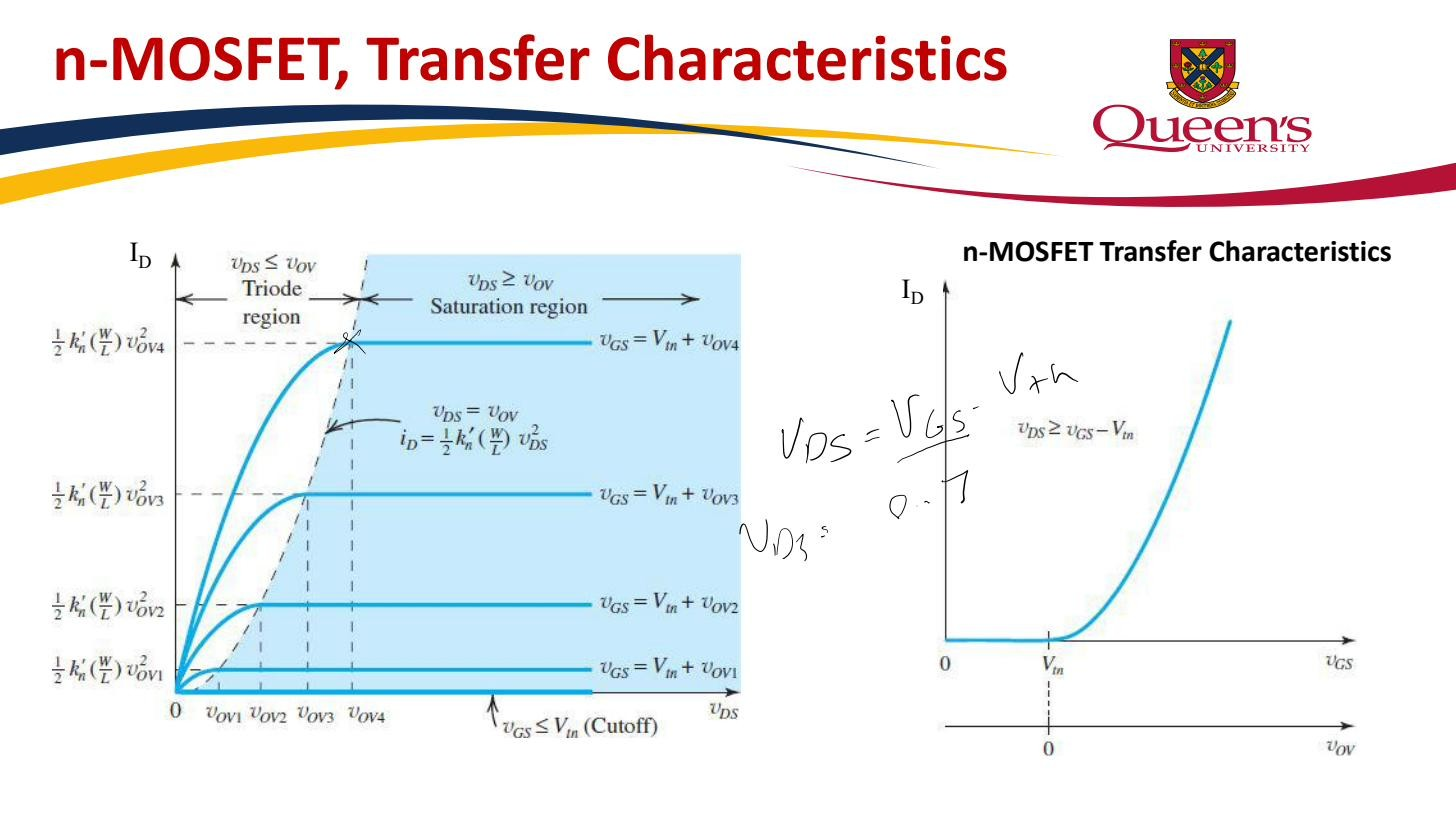 Left: – family bounded by ; right: square-law transfer characteristic.