The MOSFET small-signal model is the linear equivalent circuit that replaces the transistor for AC analysis around a bias point. It’s the nonlinear MOSFET square-law linearised about the Operating point. Valid only when the device is biased in the saturation (active) region, since it’s the linearised saturation square-law. A triode-biased device behaves as a voltage-controlled resistor and needs a different equivalent circuit.
The elements
Three pieces, derived directly from the device physics:
- Open circuit between gate and source. The gate is insulated by the Gate oxide, so no DC or AC gate current flows. Looking into the gate you see an open circuit (infinite input resistance). That’s why a Common-source amplifier has essentially infinite input impedance.
- A voltage-controlled current source between drain and source. The linearised square-law: a small produces a proportional drain current , where is the MOSFET transconductance (the slope of the transfer characteristic at the bias point). This source is the amplification.
- An output resistance in parallel with that source, drain to source. models Channel-length modulation, the fact that the saturation current is not perfectly flat with . For an ideal first pass it can be taken as infinite (omitted); include it when computing realistic gains.
All small-signal models zero the DC supplies (DC voltage sources become AC shorts to ground, DC current sources become opens). The resulting circuit is purely linear, so superposition and ordinary linear circuit analysis apply.
Two equivalent forms
The same three elements can be drawn two ways, and they give identical answers in any analysis. Pick whichever makes the algebra easier for the topology at hand:
- The MOSFET hybrid-pi model: the natural arrangement above (gate-source open, + across drain-source). The default for the Common-source amplifier.
- The MOSFET T-model: the same elements rearranged, with a resistance appearing between gate and source. Often cleaner for the Common-gate amplifier and the Source follower.
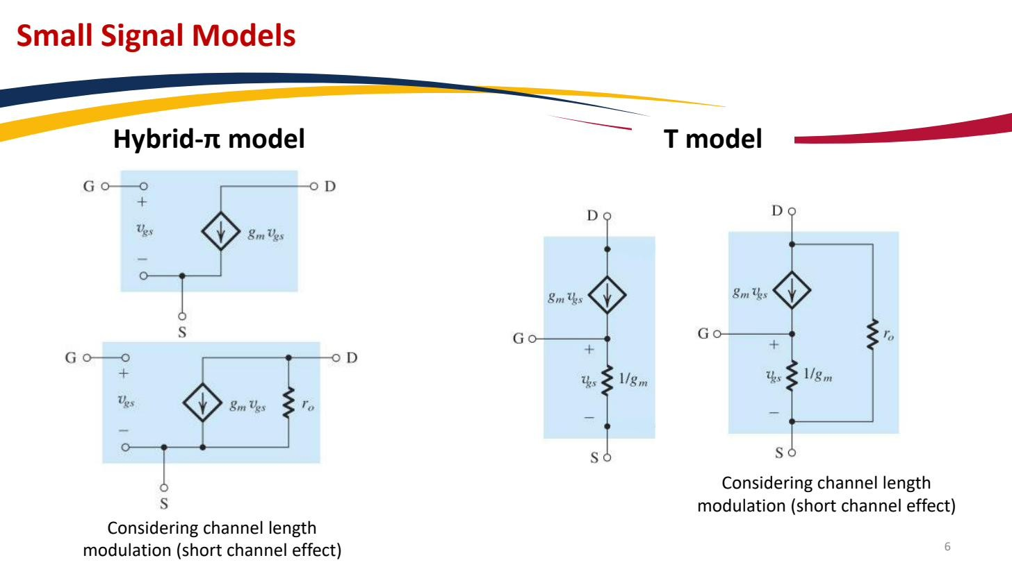 Hybrid-π and T-model, equivalent rearrangements giving identical answers.
Parameter summary
Everything reduces to two numbers, both evaluated at the bias point:
with the Overdrive voltage, the DC drain current, the device MOSFET transconductance parameter, the Early voltage, and the channel-length-modulation parameter. Get the bias point from MOSFET DC analysis, compute these two, drop in the model, and the amplifier is a linear circuit. If the body isn’t tied to the source, a second source is added (Body effect), but in the discrete circuits here the body is at the source and it drops out.